Nick's little project

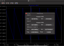
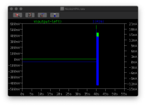
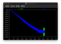
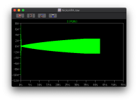
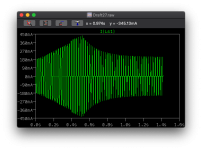
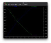
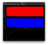
Just looking at the voltage regulators (the LT3080 Maida) seems like it's working nicely. This is the first run - it takes 36 seconds for it's soft start!
aQTctGr.png
Unloaded, the ripple at the top is 9.2mV peak-to-peak.
vPO1JoP.png

This small regulator-only ~40sec run size is 20GB of data.

So next is to have these settings setup in the big model with the timings setup so the mute is switched off after a minute. I will need to reduce the amount of recorded information and then let it run for hours.

I'm getting 9000uV (9mV) ripple but the real world voltage regulator does 20uV. However it will do for an initial run.
 
Last edited:
So.. 60 second run (over running for a an hour+ realtime) - this is a stereo run but only saving a small number of points on the circuit - 9.72GB!

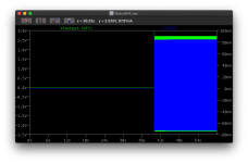
This has no CCS, just the main 200V regulator. It's also performing the 3.16V peak transient

Headphone seems decent
RDWZh7h.png
You can see the headphone mute - now set to 40 seconds, as the voltage regulator takes 36 seconds to warm up.

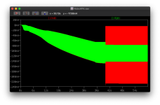
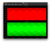
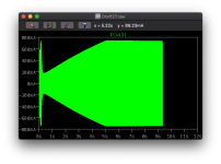
However the current in the output section current flow shows:
QAzA15v.png
* green = combined bottom current flow (where the old CCS was)
* red = combined upper current above the valves.

The valves should be idling at a combined 75mA and each valve has a max of 60mA, so 180mA combined max at the top is acceptable. The output is a little high but solvable (230mA vs 180mA) so this is looking good as a starting point for the amp. I can actually add another triode (the real life version of this will use two tubes - each with two triodes - per channel) which would add another 60mA, so 4x*25mA=100mA idle and 4x60mA= 240mA peak).

Doh - just noted that thus doesn't look right and next run in progress (overwrites). The PSU is really noisy.. hence the full wave rectification of 50Hz mains = 100Hz..

XI0VFco.png

Ok.. next run a 447mV run to compare... zzzz....
 
Last edited:
Initial results at 447mV

p1Hp6TH.png

and flow of current top and bottom of output tubes.
mIJgceG.png
So as suspected, I think there will need to be a little real-world adjustment potential (variable resistors etc). However I'm happy with that.

This run I added a 1ohm resistor in the mains line to allow the current to be recorded:

pzPHUCp.png

I don't know the power factor (until you have a transformer in mind that's pure conjecture). However 4A*230V is extremely high. And I'm not sure if I'm calculating that right.. it's more like 180W from basic DC power current measurements.

Continuous power rating: 120VA
Primary: 2 x 0-115V @ 50/60Hz
Secondary: 230V @ 0.52A rms
Dimensions: approx 91x55mm
Mounting: mounting kit

If I put this as the B+ supply, this would provide on the edge current demands for both channels - I may simply use another that I found which can provide 1.7A at 230V, which would probably drive the heaters too.

Also I may be inclined to add a second, 15V, high current supply for the heaters and to provide a 5V line for any logic level (ie the digital DSD512 later). For now I could run this off a switched mode power supply (it would need a filter) external to the box for now.

Just need to think through the transformers.
 
Last edited:
Noisy PS is noisy...

447mV 10KHz signal
8yIJKdG.png

So that's -12dB signal - so half is -3dB so -12dB is half of a half of a half of a half.

If you have a 104dBV headset it means at 1V it's 104dB .. so deafening. So we would be probably listening at 60-80dB. So ±400mV or 0.4V (-12dB) is probably not too far away from comfortable listening.. we'll have to see :D

For reference 120dB would cause serious hearing damage (ie you'd be deaf). So most people' limit of hearing is -100-120dB. So a clean noise floor at -140dB would appear dark without hiss etc.

So sorting out the PS would be very good. I may just use this for an initial regulator for the PS.


Edit: So I've replaced the voltage regulator with a 3rd order RC lowpass filter set for about 1Hz (300ohm and 470uF repeated in a chain 3x). This is providing a much cleaner voltage output - at a cost. The voltage drops from 200 to 150V. So the transformer has been step up to bring the voltage back up to 200V B+. Naturally that's quite a bit of heat being generated!
 
Last edited:
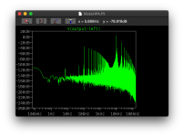
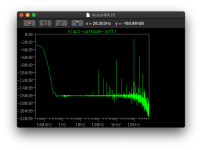
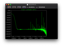
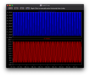
Removed the regulator and added the three lowpass filters (RC) - this is the output from the cathode line (the headphone mute has not disabled yet). I have the left channel signal set at 447mV 10Khz and the right channel signal set to 447mV 1Khz to trace crosstalk. I also added a 1Hz RC filter between input and output tubes sections for each channel.
ec0mFMU.png

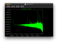
And the B+ line noise:
ec0mFMU.png

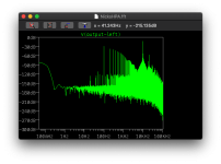
You can see from both of the FFTs above that there is cross talk through the shared B+ line so I will need to put a filter/decoupling cap between the PS and each of the channels. The above shows - <1Hz is the pass through from the LC filter. The 1Khz right signal+harmonics and the 10Khz left signal+harmonics. So we should really have some smaller filters in place to cull this (smaller uF and smaller resistors = cheaper).
DC on these plots are acceptable as they're before the output cap and headphones.

The simple 470uF with resistor seems to work nicely. (400V 470uF caps are £5 each so trying not to use them in the correct positions).

So I'm happy with this performance so far. Sometimes the old methods work best. I can now look at refining the filters and reduce some of the voltage drop.

I still (now) need to look at the bias, as there's a little current spike early on during startup and look at inrush given the capacitance is higher.

A regulator at a later date would probably improve this further.. but a regulator board at 10x the cost (ordering board from the US rather than building my own).
 
Last edited:
Cross talk begone :D This is 20 seconds after the headphone unmutes.

o82w5lc.png

So next steps are optimising the filtering, and perhaps attempting to get rid of that 100Hz full wave and harmonics.
 
Last edited:
On the subject of reducing the 100Hz and harmonics - this looks like a job for snubbers :D

rectification-snubbers

Unfortunately LTSpice goes nuts, and either throws DefCon 1 (ie chaotic model) or if you put parasitics in the transformer it then it progresses but at a femto-second/second modelling speed :eek:

As this dependant on the hardware in use, it needs to be tailored on a real system using an oscilloscope or using a little test too (example here) then we can reduce the 100Hz noise too.

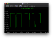
I ran some low frequency square waves - these take lots of power and the square wave shows the vase rolloff - Long and short:

Eu71n2G.png

The tops of the square wave show if there's any issues in roll off etc. This has some but I think it's acceptable. I already know the from the frequency response curve it rolls off rather than being straight at 100-20Hz - with the 12AU7s.

I also found a NPN-PNP based current limiter that would be easily implemented - this worked well so I'll add the bits in for that too.

I suppose a bill of materials list is in order :D :D
 
Last edited:
Current speccing out the bill of materials, rough estimation is currently about £300-350 (inc VAT) not including case, assuming I can get a reasonable cost 230V:230V transformer - this is with the basic non-gadgety build - in fact the only gadgets will be (a) inrush limiter but on a manual bypass switch (thermistor for is £9 for a 10A max and 600J to cope with 490J inrush) and (b) a current limiter on each channel's B+ line (NPN+PNP with three resistors). This also includes variable resistors for the initial tuning (£4 each vs pence).

The big cost items are:
* valves six ~£15 each
* capacitors - especially the non-electrolytic (ie coupling caps) - two 0.1uF 450V film poly caps (not bad but cheapie 5% caps are £4 each). The power caps can be electrolytic - the signal B+ filter caps I currently have six 470uF caps (£6 each) and power supply has a reservoir of 1000uF (£20 each). The output caps - initially I will use a low ESR electrolytic for the 330uF output cap and a poly film for the 10uF cap - the benefit of this design is that the internal rail sits at least 6-20V and the headphones AC then sits within that, so there is no reverse polarity DC at a later date.. I will change that for a large poly cap but they are £80-120 each!).
* power transformer a cheapie 230:230 toroidal will be £50.

Digital is low voltage high current, so high volumes of demand lower cost. Valves and high impedance headphones are high voltage and low current, so only need low capacitance and low current components. As soon as you go high voltage and higher current this equates to higher power and the costs go up. If you want higher efficiency valves.. then add the cost of transformers.
 
Whole set of caveats and things to iron out.

Naturally I don't advise copying this design, if you do so you do at your own risk. This is my first. This design has not be built before.

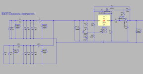
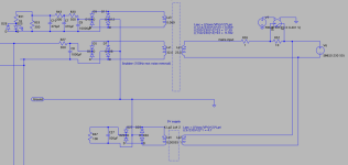
This is the current configuration. Some notes:
* For my build I'll be adding a a current limiter per channel between R48 and C13.
* fuses will be added between C13 & R48.
* The low pass is pretty basic targeting 1Hz multiple times
* there is possible way to reduce noise further by moving the ground point.
* The 12.6V I've pretty much ignored, so I will not be implementing, it's kept to add current drain to the transformer. 5V digital line will be missing too from the initial build but is there for calculating the thermistor Joules required.
* Right channel is a duplicate including the filter C13/C12/R34. If you don't have one for each channel you'll get cross talk through the B+ line.
* R12, R9, R48, R20 will be variable resistors initially until the system is tuned. It is highlighly likely that R11,R17 and R25 / R15,16,18 will also be variable as the ecc99s are not matched and may vary.
* U1 may need some matching but I'm hoping that the balanced tubes will at least be closer than the ecc99s.
* There is no current limiter shown for the heaters
* There is no negative grid bias mechanism - careful as the U2 anode voltage may rise faster than the e99 cathode voltages, this I've not checked since removing the voltage regulators.
* no bleed resistors show (100K) for each of the caps. I need to see if this changes the filter and adjust the resistor values according if it does.
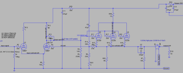
qQHXf7M.png


Power supply section
* the hard power switch, fuse are not shown
* the bypass will be a manual switch, literally next to the power switch - switch main power, count switch the other. The Thermistor should be specced for at least 4A sustained and 490J inrush so I will be using a 10A capable 600J (about £9).
* Again no bleed resistor across the 1000uF cap.
2GSYBgD.png

Those that are following for interest but don't quite follow the sections, left to right:
Left - that the mains supply - a sine wave 50Hz
The 10ohm resistor is simply simulating the thermistor, with a bypass switch, the 1 ohm is so I can easily measure the AC current flowing.
Next is the toroidal transformer
The full wave bridge rectifier
Then C8 is the 'reserve' capacitor. This is the first ripple smoothing cap. It main job is to provide a backbone for constant current output. This is why it's 1000uF (valve amps only draw milliamps not amps) but what is important is the high ripple current so it can provide output and charge fast.
Actually that R27 should really be removed, and put in front of each of the low pass filters - currently that's why I get a slightly worse noise after making the change for cross talk (just spotted that!).

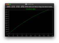
Given the current setup a 447mV signal actually outputs 386mV signal. This represents (if my calls are correct) a -8.27dB attenuation (naturally providing more current power). So my 104dbV (ie 104dB per 1 volt) headphones would be playing at 97dB .. plenty loud enough!
 
Last edited:
Valves ordered, currently progressing through the other components.
2x 12BH7A-STR as input tubes
4x ECC99 as output tubes

So for the capacitors - given these are 450V rather than the smaller things you find for 3V etc. These will be:

2x 0.1uF decoupling caps - Auricap XO 450V 0.1uF
2x 10uF bypass output cap - Auricap XO 450V 10uF
2x 2x330uF 450V output cap - Panasonic / Nichicon Electrolytic low-ESR 450V (these will be in parallel)
6x 470uF 450V B+ filter cap - probably the same Panasonic/Nichicon or KEMET.
1x 1000uF 450V reservoir cap - this is likely to be KEMET
Caps clamps

Resistors - all metal film rather than older carbon composite
Low current signal path - probably Vishay
High wattage - probably TKD

Variable resistors (tuneable pots) - these are used to find the fixed value resistances or tweaks for individual tubes.
Bourns 1K and 10K 550V one turn cement 2W pots.

Rectifier - these will be rectifier bridges rather than individual diodes.

Wiring will be 600V hookup wiring.

Solder - low temp (ie about 200degC) so this is likely to be Jansen 4% silver stuff.

Edit - I thought I'd check the wattage rating and current for the caps.. first cap current is a little high, so some mods needed.
 
Last edited:
Currently focusing on the inrush and power management - 230V power management quickly escalates.

My initial design of filters and caps had some serious issues - when you look at the power dissipated it would lead to component failure. Although components can typically cope with a cycle or two of inrush, they can't cope with extended periods. So the power needs to be managed.

I have my eye on a 270V 600mA secondary transformer (210W but also supplies 6.3V so there may be a better transformer for my purpose). So the maximum current I can let rip is 600mA, not amps. So the idea here is to put a current limiter in here - limiting under the 600mA but enough to support both channels. So all the models with 1-4A of current at this stage need redesigning a little.

There's two stages for this - pre-transformer (using an NTC for cold starts) and limiting the current between the transformer and capacitors.

This is the managed power draw on inrush start up - 450mA may not sound like much but then multiply that by voltage of 200V to get watts. The I'll be using a 600V 10A capable MOSFET with 156W max power dissipation, the calculated dissipation here is about 30W from the mosfet. This limits the current draw at start and during amp operation. The issue here is - do I want to be dissipating 30W continually as the system is always drawing current (Class A).

Hnd84Q3.png

I still have some design work to go.

So I've been trying RC passive filters, the issue is simply that the current limitation and voltage drop result in needing serious power.

560mA at max capacity *(ie all fully open valves on both channels) at 200V.. with 300 how resistors in for RC low pass filtering results in a 440W power draw - attempting to bunk up the transformer voltage of the secondary has little effect, as the max current I can pass (unless I simply shunt the current) is 580mA. 560mA.. limited and RC filtered a couple of times means 450V drops to 150V.

There's a formula in terms of current load and capacitance for AC mains, to achieve a specific Voltage drop per ripple. So this basically shows the same issue given current and resistance are related to voltage. It's hard maths. Go one way and you overload components wattage, go the other way and you don't get enough ripple suppression. So next stop is to look back at the low drop out voltage regulators.

Just at what is 1/2 amp at 200V, that quickly becomes large wattages (400W).


Edit: So I'm now reattempting the LT3080 low drop out regulator to see if I can get the right current and voltages with minimal drop out.
 
Last edited:
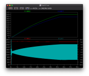
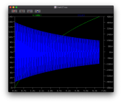
This isn't too bad - 140V peak-to-peak regulated to almost 2V peak without big caps:
kFf3kfL.png

So I'll retry with some pre-smothing reserve caps.

Vripple = Iload / 2*freq*C

So if I want 1volt ripple at 600mA (combined both channels is 540mA maxed out) with a 50Hz supply: 1.0V = 0.600A / 2x*50Hz * C farads.

Rearranging C = 0.6 / 2*50*1 = 0.006F or 6000uF for reserve. Sounds small compared to solid state amps but these are 450V caps.

However let's see what we get from the model with a 6000uF cap before the voltage regulator:

BuDBzzb.png

Well the model is early and the top trace is what I'm interested in - not the arc but the saw tooth ripple.. that's about 0.04V or 40mV of ripple - better but not the uV that was being talked about. Only issue with this regulator is that it takes about 30 seconds to soft start (hence the green trace is 6V).

Given the B+ rail reduces in current demand as the B+ rails supplies the front end (only 40mA, plus buffer, say 50mA per channel), we can reduce the size of the capacitors if they're overkill. Let's have a look.. but as we're not interesting in a 1V ripple on our input tubes, we need to look at something smaller. Perhaps 0.001V or 1mV.

0.050 / 2*50*0.001 = 0.050/0.1 = 0.5 F or 500,000uF. Hmm a room full of capacitors perhaps.

If we look at our trusty 470uF caps, we get a ripple of 0.050/2*50*0.000470 = 0.050/0.047 = 1.06V.. however we're using this as a Low pass filter - where a 300ohm resistor followed by a 470uF capacitor gives a cutoff of 1Hz.. a nice mechanism to reduce noise - both cross channel but also ensures that the ripple noise we do hear is under our hearing (almost DC). We could actually reduce this stringency to cut under 10Hz and you'd not be the wiser. All we need todo that is simply change the 300ohm to a 30ohm with the bonus that we don't see such a voltage drop out.

This is one of the best set of filter design tools I've seen - CRlowkeisan.htm and the RC filter helps me locate the best possible filter without too much voltage drop.

This is what the supply looks like at the moment - the resistors are simple models set up to pass ~60mA at 200V each and the front valve resistors are setup to pass ~20mA each.
2KV3FHf.png

This doesn't have any signal modelling that a valve model would but then the data produced by a full model is too large - this describes the problem then I can move the fix to the larger model for verification.

At the moment C5 and C7 don't have the resistor in place for a LPF, simply there to see if I can get away without the voltage drop.
 
Last edited:
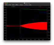
So run finished.
agLkw8H.png

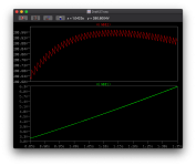
Top - green showing the ec99 B+ and the blue showing the 12bh7a B+. The gap between them is caused by the 300ohm resistor for the LPF.
Bottom - Input into the regulator and the current draw.

Something isn't right because a low drop isn't 50-70V! I can get better with a small passive filter!

For the record.. that's about 2000 Watts according to LTSpice.
 
So this run with 6000uF reserve capacitance and no further smoothing capacitance after the regulator

L9Y3e7M.png

Blue - input into the regulator - basically 1V peak to peak as calculated
Green - output from the regulator 0.08V peak to peak.

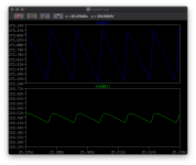
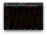
Starting to play with the values of the resistors etc. If I switch to measuring the current, at 218V, the current is 0.22mA peak to peak. So I'm wondering if a small capacitor after providing say 0.22mA after may help.

It should be noted that the tops of the current ripple are 100Hz (about 7-8mS) also the peak to peak is 227uA

So C = 0.000227 / (2*100*0.08) = 0.00001418 farad. Or 14.2uF

If you put a 1 ohm resistor in front of it you get a 11KHz low pass filter.. *bing ideas*

Increase the capacitance to 140uF and use a 20ohm resistor and you have a 11Hz low pass filter.. with the 20ohm being virtually no voltage drop and the small 140uF doesn't seem to cause the voltage regulator to become unstable (ie larger ripple).

RZexQbU.png

So this is the current and voltage.. looking very very good.

Ok now the bad stuff...
EftSUKx.png

2KW.. Hmm seems odd, also need to drop the voltage so we're only running a smaller loss so starting through the setup.
 
Last edited:
Now going down the pre-charge route - keeps the inrush to 400mA and spends 20 seconds charging the 6000uF capacitance to 200V before starting..

flb3CZL.png
 
osKPwg2.png
So the 20s precharge works, the you can see the soft start (a minor 25A blip) and then a slow ramp up to operation. The +/-5A is through the transformer.. it’s a good 550W avg power.. hmm

I’ve asked for some help over at the DIYaudio forums to try to identify the reason for the current sucking. I suspect that it’s heat dissipation from the Voltage regulator.
 
Last edited:
Right.. so I've worked this out - what is causing it, what it means and I've thought and modelled a possible solution.

The large current is due to the capacitive load. This causes 'cresting' ie a thin current spike vs the wider sine wave. RMS (ie sqr(2) or 1.414) is based on a sine wave, not crest. So crest factor = current peak vs current rms, which is basically about 10x. Your PC is about 2-3x and this is also why switched mode PSUs don't like capacitive loads. It also means you have to spec your transformer for the crest.. ie 6A.. or 230*6A = 1.4KW.. yeah and having a tax accountant wife.. that's going to be hard to explain when the electricity bill arrives..

A good description of the problem here: http://blog.powerandtest.com/blog/what-is-crest-factor-and-why-is-it-important

So that got me thinking - if a RMS current is a wide sine wave, why can't we flatten it? We only need 0.6A not 6A! We have capacitors and with enough extra mA to cover any ripple, it should be fine and allow us to use a normal sized. If I use a current limiter - there's no resistance up to the set limit and the transformer sees a capacitive load it can handle, but above the limit the transformer sees a resistive load that doesn't want current.. transformer happy as Larry.

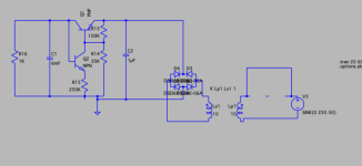
So I made a test rig:

DumSxek.png

And the current wave form at the transformer (green) looks good.. far far closer to RMS and the power required (red) is peaking at 160W.

CqkP6Qf.png

So what does this mean?

iMFmoRk.png

The limiter is set to roughly 800mA, this could be reduced towards 600mA
Red = current at the secondary of the transformer (this was 6A previosuly) is looking healthy
Blue = current at the output pin of the current limiter is looking good - enough to supply the amp
Green = the voltage B+ rail of the amp is the desired 200V.

Result!

We're not out of the woods just yet, voltage regulators require a minimum voltage so we need to be careful - the little 1uF cap is there to provide an initial voltage stability for the regulator MOSFET and a soft start thermistor would help the first few milliseconds of startup current limiting. In operation the mosfet is dissipating 20W of heat but at startup 4 seconds this is 140W as the cap charges - given I'd use a 900V 10A piece here capable of 156W max dissipation this would simply be warm attached to the heatsink but the thermistor will help break that initial power spike.


So I've added this to the amp power model.. added a 0.1s bypass pair of 30ohm resistors in series to simulate a thermistor on the mains side of the transformer to limit inrush. It's looking good currently for the secondary current draw:
FaRk5OF.png
 
Last edited:
Always, some simply guidance and numbers from the more experienced folks over at diyaudio ..

Typically all this 'spikiness' is fudged into the rough calculations so this is all a bit of a red herring.
 
V dc = 1.4 x secondary Vac
I dc = 0.62 x secondary Vac (from the Hammond website)

So for 200V DC at 600 mA (= 120VA), you need a secondary rated at 143Vac at 0.97 amp ac (=139VA). You have to add regulator losses on top of this.

So given the regulator etc needs a load more (excuse the pun) - typically 20-30V drop and some current to match.. plus we don't want to be running at 100%. So my regulator starts with 220-240V. The issue here is you can make VA calculation but then you have to look at regulation (ie treat it as a drop) and plan for a 10% drop in mains voltage. So roughly you want 15% more on top of the regulator drop.

I'm currently eyeing up Hammond toroidal transformers.
225VA -> 234Vrms CT @ 0.96Arms (CT is useful for different topologies) we're too close on the current..
225VA -> 220Vrms CT @ 1.02Arms. 7% regulation. £65.
300VA -> 240Vrms @ 1.20Arms. 5.6% regulation. £73 but a 4 week wait for stock.. 4.88" across and 1.8" deep.. 2.7Kg. It's only a shame that this isn't CT - then I could use it for push pull later..

I suspect the 300VA would be more than enough. This is for the signal path only.. the 12.6V heaters will be additional watts from a second transformer (probably a brick for now).

Got to love OTL.. I could run a normal valve power amp. Not too late to switch to a couple of output transformers :D Small personal headphone amp..

Valves arrive tomorrow so looking forward to some shine glassware. Although I'm not going to risk setting them up on the block PSU until I have a current limiter in place.

Still looking at transformers.
 
Last edited:
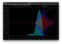
So the start up is in three sections.

1. 0.1-0.3s of resistors emulating an NTC - this combats the current inrush into the primary side of the transformer as it magnetises.
2. 0.2 - 2.5s - active secondary inrush limiting - instead of a large 10+ amp spike this is now averaged over a few AC cycles (blue peak current) - with a max of about 3.5Arms (red). Green shows the secondary side voltage. During this time the MOSFET feels a spike of about 440W for about 0.2 seconds (teal colour) - this heat wouldn't have even got to the heat sink yet..

TYWbjZx.png ]

So I still need to see if the mosfet will handle it.. but I suspect it will.
 
Back
Top Bottom