Project Whurple - White/Purple Watercooled Build - Changes to 3d printer build!!

Use your endstop to let the board know where X Home is. That should then reset your X 0 position to the end of the extrusion and give you full range of motion. Disable steppers in the menu, roll the carriage to the end of the extrusion and then auto home. When the carriage smacks the endstop (and it will smack so hold tight or mount it :p ) the board will have its home set.

Essentially you can't do negative movement so you've set your X 0 to the middle of the extrusion just by virtue of installing the carriage there.

As for X Max, I believe that's something you'll need to program into the firmware.

You were spot on. Last night I thought now that I have managed that how about I give my old printer some open heart surgery and reconfigure that board and LCD into my old printer and re-write all it's firmware so that I have at least one working printer. Was a bit of a nightmare as the old printer board uses HICTOP endstops and this one doesn't and has 3pin endstops (with reversed logic). You can probably do something in the firmware to get it working with the 2pin endstops but for now I put the new ones on the old machine and have managed to home it successfully on all axis. Not a bad job all considered and the firmware is now fully configured for my little i3 clone!

The following video was for a friend who was wondering how small a step the motors can take but it shows some progress :)


I forgot to film it in landscape... Animal!
 
Last edited:
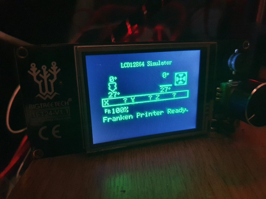
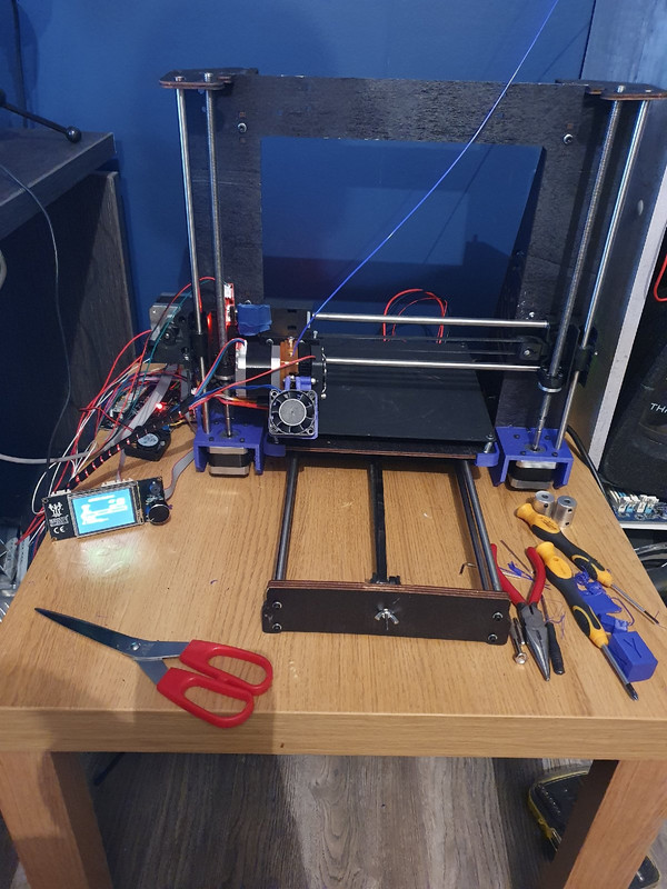
After much messing about we are back in the printing game and are printing stuff for the new build. I spent what I would consider a significant amount of time messing about with all things software and now have the firmware properly dialled in for what has become affectionately named "franken printer". Right now the new lcd is working in simulation mode as this new lcd (not the one in the video above) is the full touch screen capable TFT so that is the next thing to get properly working. There were many issues along the way, for some reason I was convinced that the motors were 0.9 degree 400 step motors so I was doing all my calculations with that in mind so you can imagine the confusion when this happened:


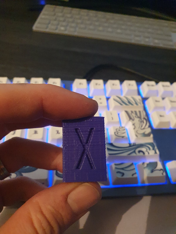
Also here are a few pics. I think I have everything properly dialled in now, from esteps to whatever else writing the firmware to make a board work with a printer from scratch was a bit of a chore:


It looks proper fallout right about now but things I have replaced on this little printer include, end stops, extruder, hot end, motherboard, lcd and a lot of the wiring. The plan I think is to rebuild this one with some new printed parts such as a case for the board, different lcd and some other bits and clean it all up while also printing parts for the new extrusion based printer, for that printer I have now settled on an extruder, not wanting to go full bowden for now I have decided I am going with the Titan Aero so I have one of them on the way as well as one of the small pancake steppers which should keep that x carriage nice and light on the new printer shaving off two thirds of the weight.

I have also been sharing updates with a couple of mates and we have set up a little thing, the deal is, friend number 1 (Alex) buys printer from me for half of what I paid for it (£35) but the catch is he makes his own printer with it then sells it to another one of our friends for half of what he paid for it, but again that person agrees to make their own printer, so far there are 3 of us who are game. They will likely need help from me on the firmware but it could end up being fun and should be interesting to see what they come up with. Alex is an engineer so I am expecting his to be a fair bit better than mine. I also dropped the ramps plus mega2560 board on his doorstep while out shopping and he has made a start on his camera slider build.

I have literally gone from somebody that has never done any work on an arduino before to now having a pretty fair grasp on how the marlin firmware works. I even wrote my own routine for a 3rd fan. To say that a default flash was miles away from the settings required for this little machine is a bit of an understatement. I am now thinking with my new found knowledge that I should have a better shot at the gt2560 board as I have now found a schematic for that board as well :)
 
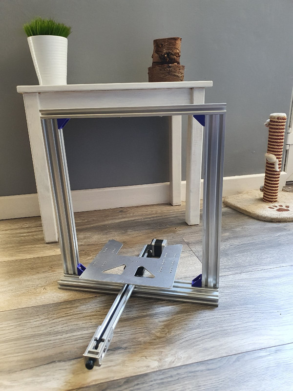
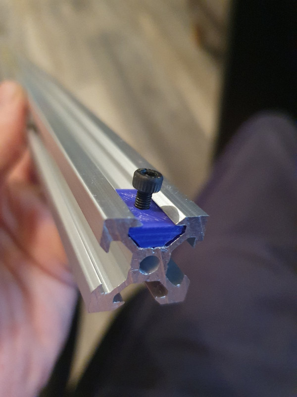
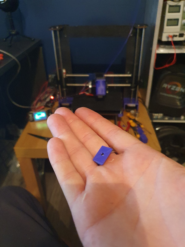
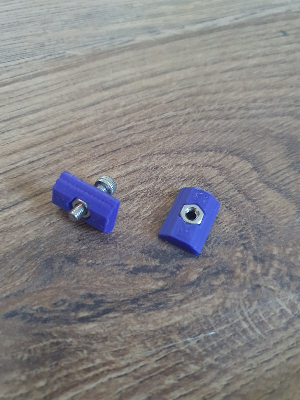
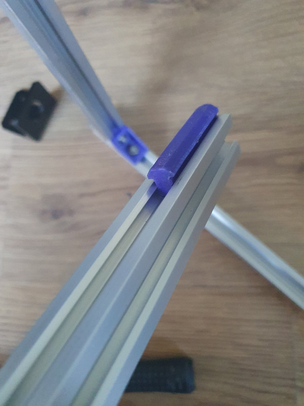
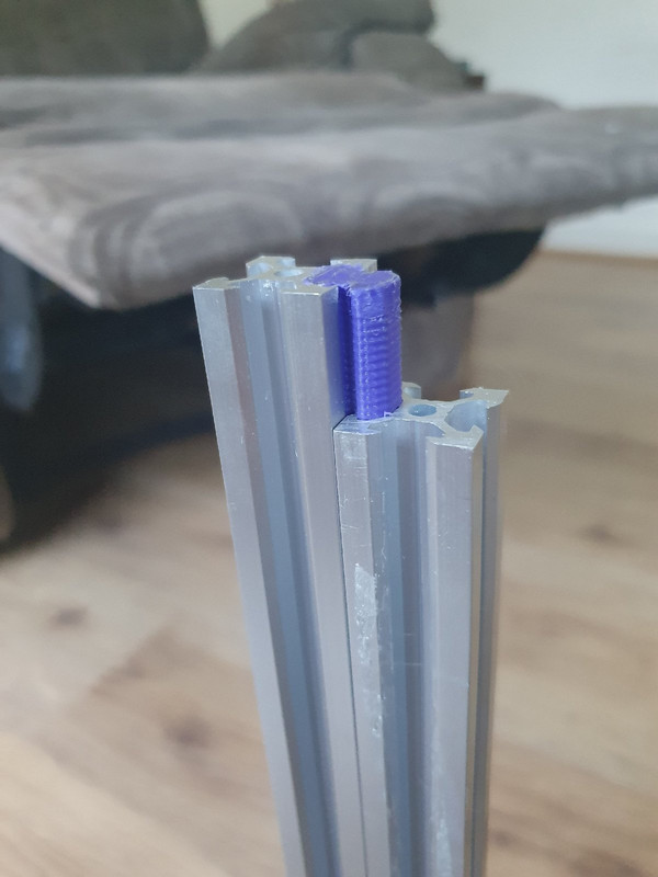
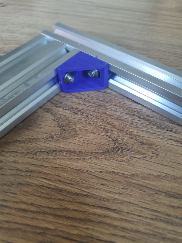
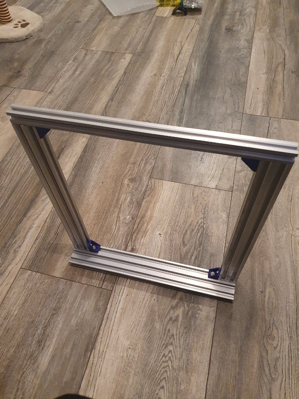
Right some updates as I have been printing some parts and starting to put this thing together. Also some new parts have arrived notable enough to post about so I shall share a little update with a few pics, firstly the build, i've been printing parts then tuning the printer as I go so some of these parts are looking a little jaggy, here are some shots of how i'm constructing this thing, once im finished ill do a full list of parts plus the firmware etc in here if anybody ever wants to build it:


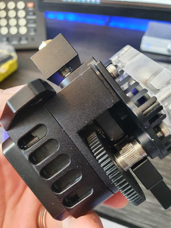
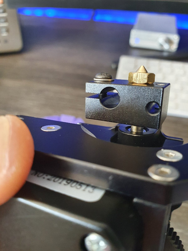
The extruder I am going to use, at first I wasn't sure because its a clone of the Titan Aero but now I am just going to roll with it and for what it cost ill suck it up and buy direct from E3D next time, anyway it is a geared direct drive extruder with a 1:3 ratio:


Its also super light and has a mini motor (pancake motor i think they call them) that should keep the weight down on the x carriage.

Next up I think I am going to work on the bed as I have a new bed and some other bits that I haven't got pics of yet. Hopefully more updates tomorrow :)
 
Last edited:
Homebrew = learning and much more fun!

Exactly and i'm mixing it up between random parts for random printers, for example my x carriage is pretty much going to be all ender 3 - I have an ender 3 carriage, BL Touch (clone) with ender 3 mount and also you might notice that the titan above has an ender 3 bracket (this was luck more than judgement) so basically everything X is ender. Then I was working on the bed and had already bought a ally plate in Prusa i3 style which looks like a U but then I saw that there is an ender 3 pro upgraded bed kit that looks pretty damn nice, much nicer than the i3 jobbie so I have ordered that in as well.

It will be rocking full touch screen capabilities, auto bed leveling (if I can get it working) plus a load of my own custom stuff I have been working on such as boot graphics etc :) Should be pretty cool! Again will make a full part list, firmware and everything available. Would love if somebody else actually built it!
 
Truly living up to the name "Frankenprinter"

Or the Vince i1 ;)

There has to be a better name in this somewhere! I am sure that once it is built it might reveal itself. I've lived my life with the name Vince and I wouldn't wish it on the little printer. Most of the time the name is fine but there are times where it feels almost impossible. Take for example ordering a Chinese, should be easy right? Wrong. It's fine until you get to the name, at my local Chinese it went on for so long trying to tell them each time I rang that now they think my name is Ian, I am not even joking, one day after many many times telling them my name at the end of the order the guy on the phone asked my name, I said Vince, he said back to me Ian and I just said "why not yea that will do". Anyway that seems to have stuck so now my name is Ian.

Same thing happens with Indian call centres for some reason the name doesn't seem to be one that translates well.
 
I feel your pain. I'm Ross but I've put up with Russ and Roz many times before. Ruth was a stretch though. Still, could be worse. Old work colleague is Glyn and he's had Glen, Lyn, Gwyn, Gwen, Len and...Clint :confused:

Never could work out why my missus Kelly is "Miss T" at the doctor though...
 
I feel your pain. I'm Ross but I've put up with Russ and Roz many times before. Ruth was a stretch though. Still, could be worse. Old work colleague is Glyn and he's had Glen, Lyn, Gwyn, Gwen, Len and...Clint :confused:

Never could work out why my missus Kelly is "Miss T" at the doctor though...

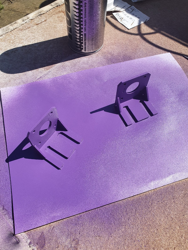
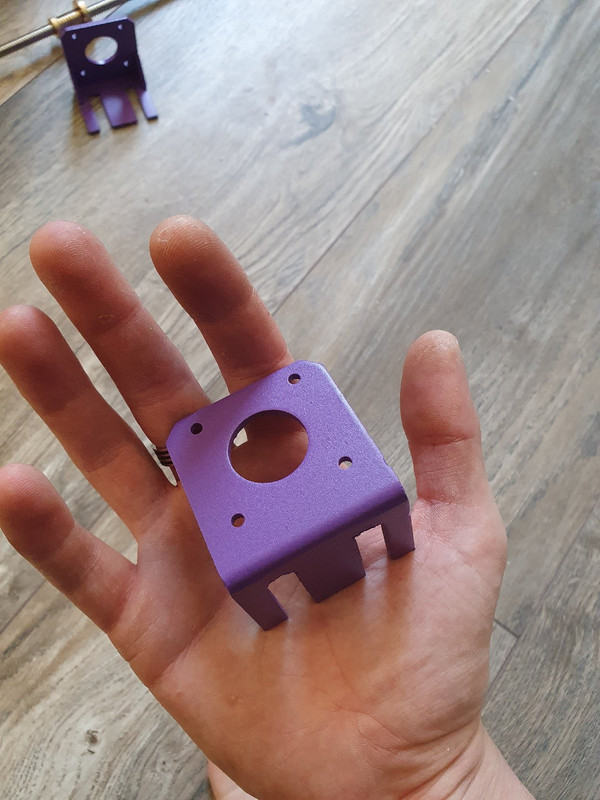
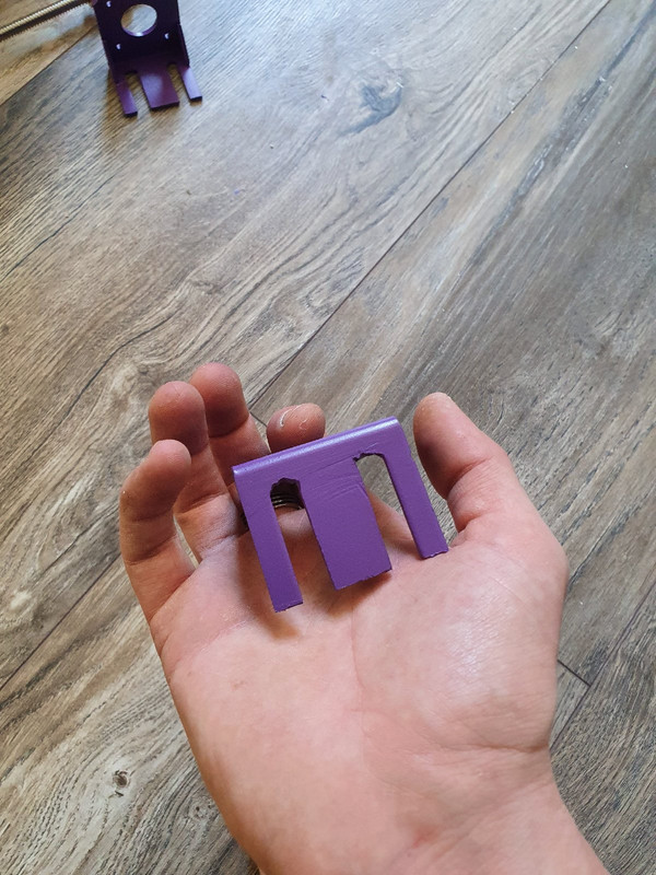
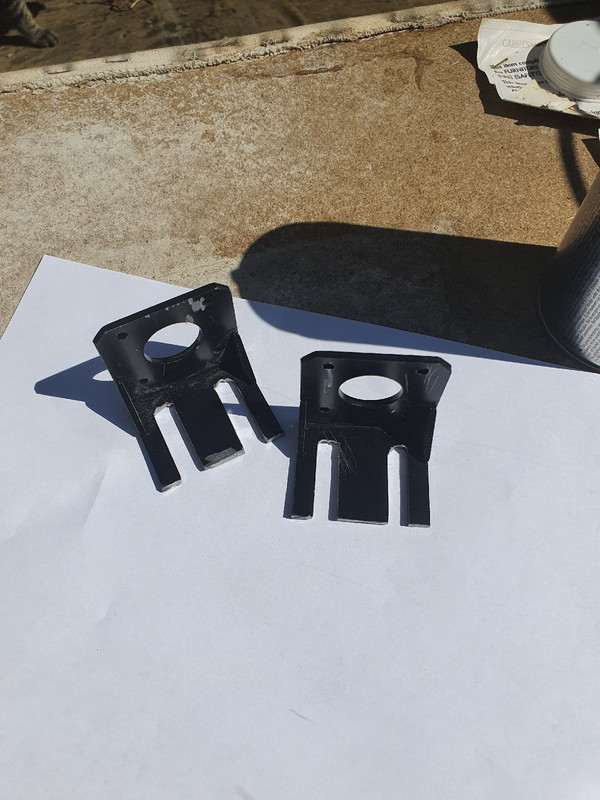
Brilliant so it isn't just me. :) I took a half day at work because i've been being hammered and it looked pretty clear this morning, the queue was clear so my one remaining support guy didn't have masses to do. This means I can play! So I started looking at the z motor supports. I'm not happy with how they were in that the mounts didn't quite line up with my build. I was thinking I will design and print some new ones (eventually I will and by the time I put up all the parts there will be some motor mounts in there) but for now I decided to get out the angle grinder and do a quick and dirty fix to my problem.

You can see what the mounts used to look like in one of the pictures last night, once id finished with the grinder I needed to give them a quick coat of something to prevent the rust so ive still got some purple paint ;) When it doesn't fit you gotta make it fit right?


Also im starting to mock up the bed, I think a single rail would work quite well and am just working out the best mounting method, I'll probably wait until the other bed gets here as well just to really work out how that might sit and what sort of mounts I need. I noticed the kind of mounts im thinking don't already exist on thingiverse so will probably have to make them all up myself.

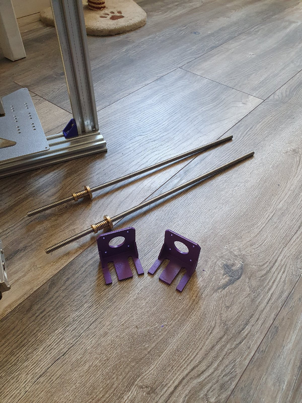
As for the rods you will also see that there are some very nice T8 2mm rods complete with antibacklash nuts waiting for the build, I also have some 8mm pitch rods on the way without the antibacklash but to be honest I will need to do a bit more research here to work out what is best. Right now im thinking the ones in the picture just seem right to me.

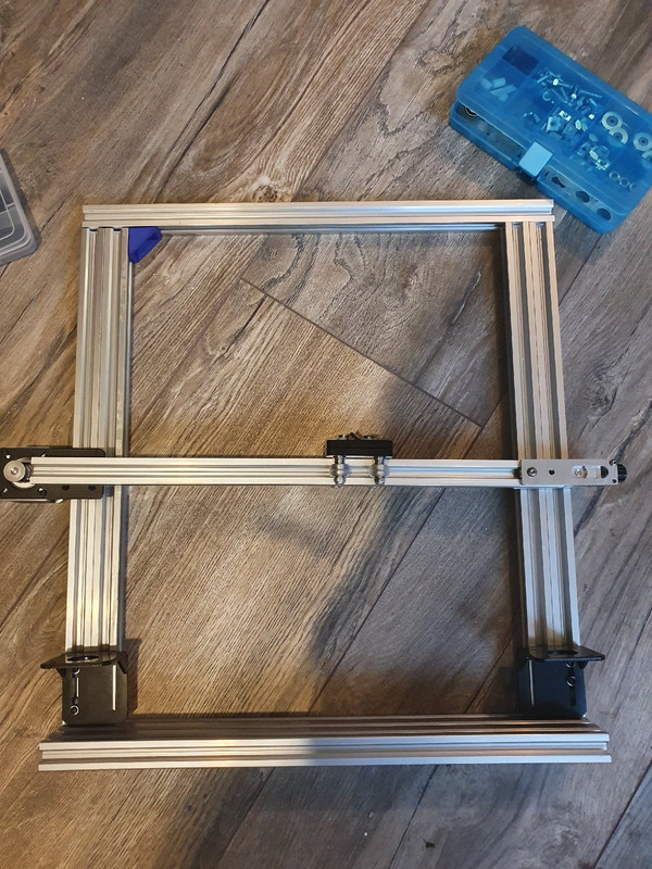
I am also trying to work out the x axis mounts as I haven't ordered anything for that and am in two minds of how I want it to be. I could go with similar to how the ender is but am not sure I like the mounts and would also need to consider the dual z axis shafts. There is another printer out there that uses 2040 on that axis and its called a Tronx (? I think) anyway that uses something similar and somebody has set up a brace part that might be a good starting point:

https://www.thingiverse.com/thing:2275654

Im thinking design a part that is flat to that and brings that into a more rectangle shape where I can then start adding the things I need onto it, so a motor mount, somewhere I can attach the x rail to, perhaps a place for a guide pully, I dunno, I think I will print that part, see how it works and then start designing my own parts :D With the right design on these it should be able to print on any size bed up to about 350mm squared or if I do dual rail you could go anything upto about 500mm x 350mm. The bed I have with the glass, 150w gel pad etc is 220mm squared so that's what I will dial it in for at first but now ive measured it up against a bed I kinda feel it should have got a bigger build surface.
 
Last edited:
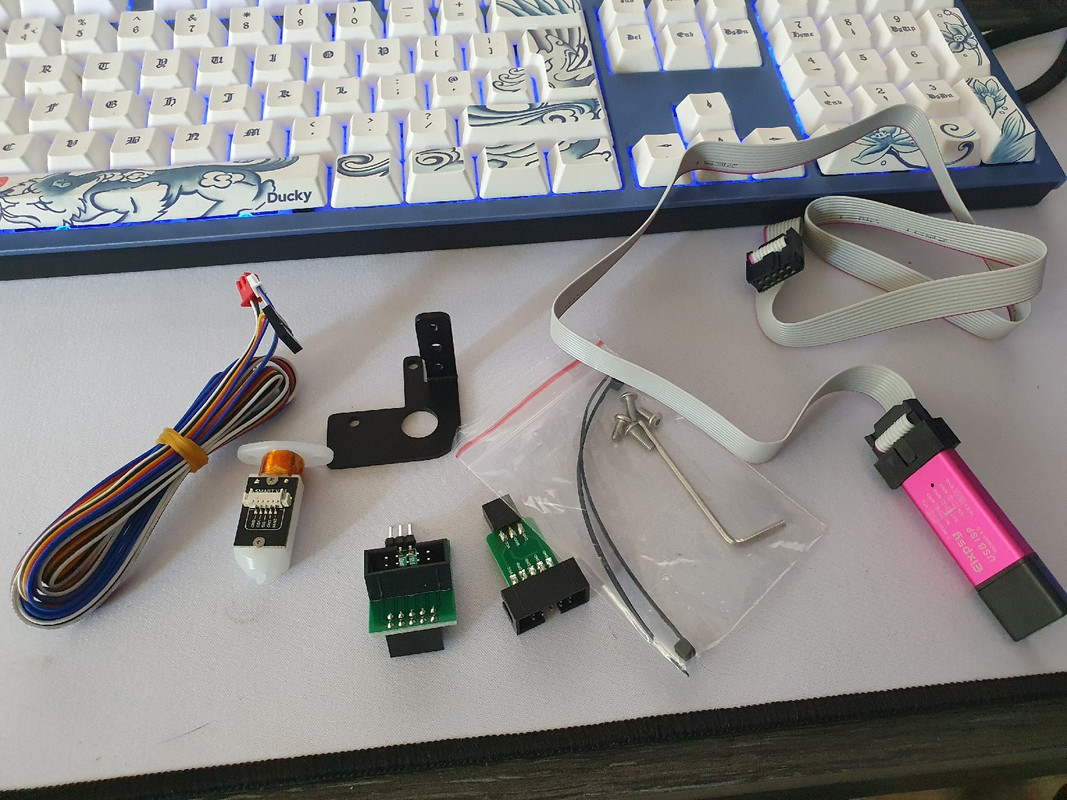
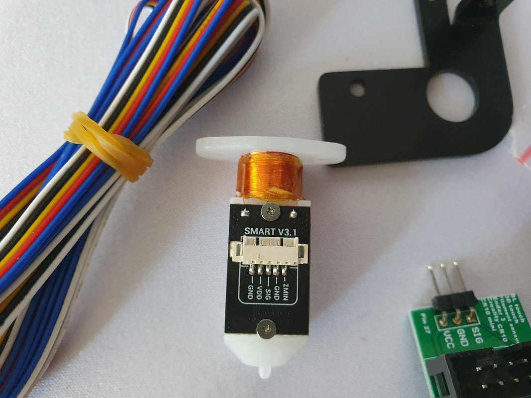
This came:


Auto bed leveling here we come. Seems simple to set up and install to be honest. No idea why I might need a usb or the extra boards, no idea what any of that does. Anybody got a clue?
 
Depends on the board you are installing it on.

That's a Creality upgrade kit and there boards don't have a bootloader, nor a set on pins for it so that what the extra bits are.
 
Depends on the board you are installing it on.

That's a Creality upgrade kit and there boards don't have a bootloader, nor a set on pins for it so that what the extra bits are.

Ahh well that explains it, I don't need any of that stuff but the ender 3 mount will come in handy as I think i'm going to run an ender 3 ish x axis. I will be running it on the skr 1.4 turbo i think and that seems a pretty simple install and firmware update.

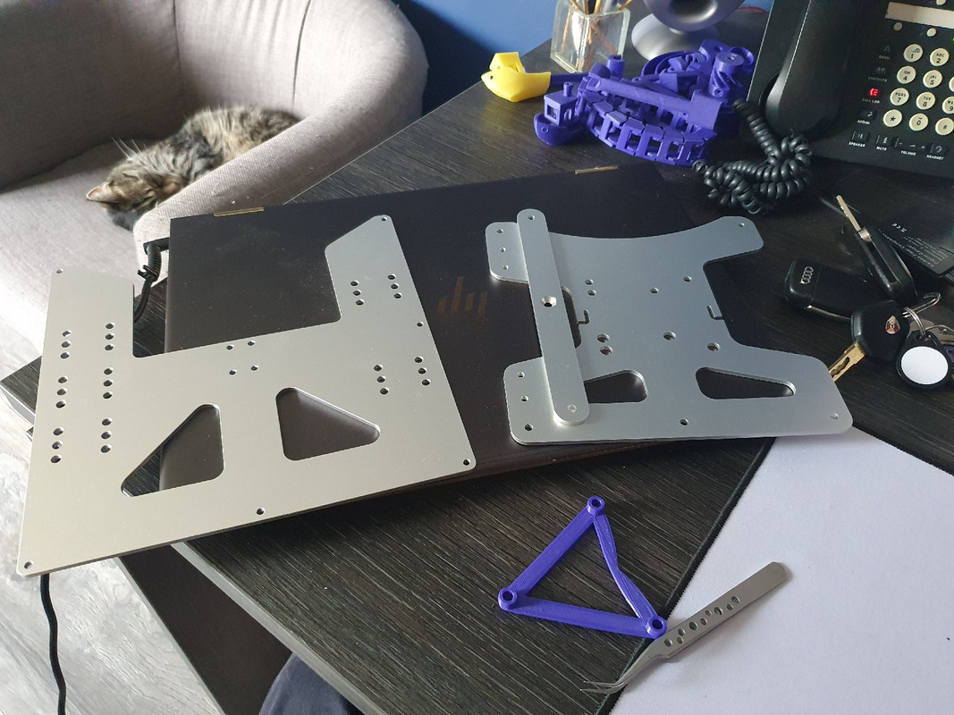
Also late in the day but another thing also turned up:


The bed is the ender 3 point upgrade bed and to the left is the Prusa MK3 3 point bed, I have been massively tossing up if I should go m8 rods and the Prusa bed or extrusion and the ender bed, problem is how small is that carriage plate on the ender bed, its 190x190 whereas the Prusa plate is 220x220. My aim on minimum build size is 220x220 and the machine is capable of around 320x500 which would mean I would need some sort of corner adapters on the ender plate to make it bigger. I'm not really sure what I am going to do yet but having them both here to measure and play with against my design makes the decision of what to do a lot easier so I think more playing and a bit of measuring I will come up with something. I was thinking of perhaps drilling some ender shaped holes in the purusa bed and be done, or drilling no holes and designing a simple bracket to sit on top of the ender one. I dunno so many ways to make this work but not many ways to make it work while keeping the bed leveling nice and simple. It's also an all glass top plate I have so leveling will be from the bottom.

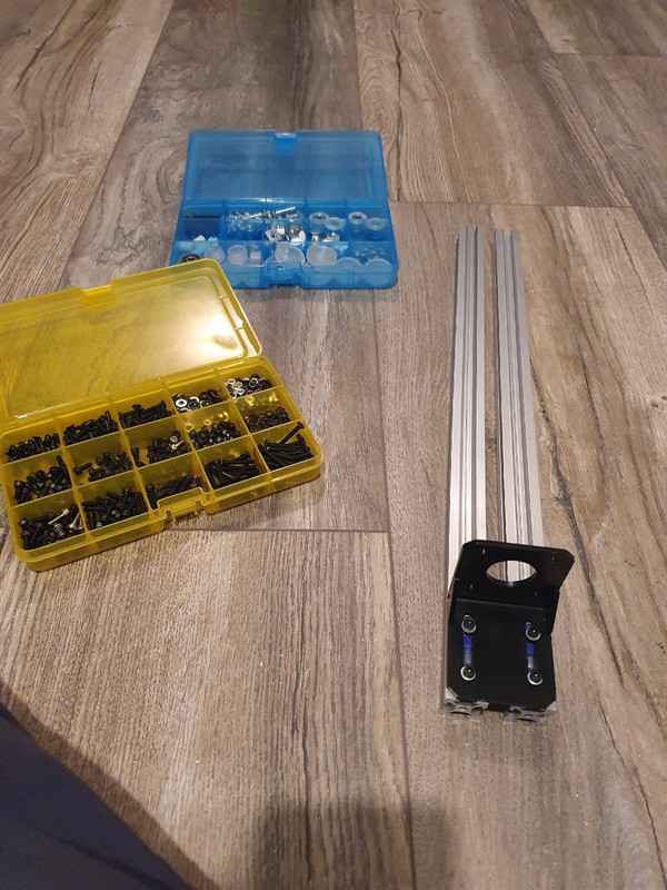
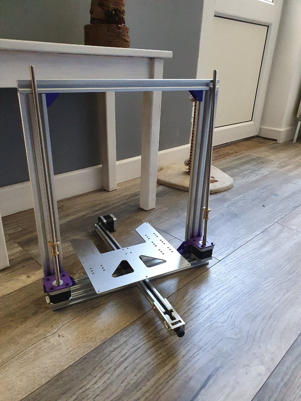
There is also some progress, Z axis motors are now mounted and ive rested the rods so you get an idea:


Lots of electrical cable has turned up, purple and blue stuff stuff to replace some of the cheap arse wiring that comes on some of these parts.
 
Last edited:
nice stuff
though the cats not over excited about it lol

He was out playing all day so came in and passed out on the chair next to my desk. It's basically his chair to be fair. Have done a load tonight including printing out some parts of the Z axis, in fact one part is on the printer now, all the runners are done and the printer is doing its thing but is a 3 hour print so wont be able to see what it's like until the morning. It might be decent, might be a bit rubbish as I just quickly threw it together in cad as a test part motor mount z mount type thing. Ill share some pics as I go.
 
Back
Top Bottom