PWM to Analog converter circuit

Great Job Tealc. I was wanting to use your circuit to control a solenoid valve (which opens up linearly based on input voltages 0-12V or current from 0-155mA) I am going to be controlling the solenoid using an Arduino/PWM. I was searching google and found your post. Of all the google links i liked yours the best.

I was just wondering that woulld it be possible for you to post VeroDs Schematic or maybe Multism schematic. I have read your post and I know the pnp/mosfets to use. I am not an EE major and dont understand the connections. So a clear schematic would be great. Thanks.
 
So the other day Jay Psi asked me to make a PWm converter for his Gelid Icy Vision. I had a Version 2 set up with a 5k potentiometer so utilised that. Laying out the boards takes only minutes.

P1050423.jpg


I only had one 4 pin graphics card connector and already I'd built that onto another converter, but it hadn't been paid for so off it came and onto Jay Psi's.

P1050426.jpg


Thought I'd try out an alternate heatsink to see of it has much of an effect. The one on the left was donated by Resident and is lovely but just a tad too high, and would push the item over the magical 25mm. I decided to fit the blue one instead and see how I got on.

I wasn't too keen on the thermal pads holding the sink on the transistor when other forces are at play, such as the outer heatshrink so decided to shove a bolt through it. The trouble is then it just makes it larger so I could just have gone with the other one.

The aluminium coloured ones will be useful but will need trimming down first.

P1050432.jpg


Because I couldnt get the sink flat inside I added a blob or two of solder to aid in thermal transfer from the hotter bolt to the cooler aluminium.

P1050434.jpg


And here it is all shrunk up.

P1050436.jpg


And a shot of the potentiomter trimmer that adjusts the speed range of the fan.

P1050438.jpg


I've set this converter up on 0.45A of fans and it ranges from around 4.5v up to 11.7v, that's 550 RPM up to 1600 RPM on my 1600 fan. I don't know what the Gelid Icy Vision fans actually use though so it might be quite different in the real world.

To set the converter up to your desired speed you will need to monitor your fan speeds and this can be done with GPU-z or perhaps Speedfan.

It's easier to make adjustments when your system is idle as the lower speed is the more critical one. Clockwise will make the fans run slower and Anti-clockwise will make them speed up.

Once set up the converter can just be left to do it's thing. It should only take a minute or so to set up and then your Graphics card will control the fans for you.

Here's a shot of testing on my graphics PWM with my 3 Yate Loons. Had it there for a good hour and the sink was warm but easily comfortable to hold.

P1050445.jpg
 
Last edited:
Looking good Tealc. It's a shame the alu sinks are a little too high. Whilst I was researching those I did come across some lower profile copper ones that were a tad more expensive.

I'll send you the link in case you want to order a set to try.
 
A small vice and fine bladed hacksaw would make some nice 2 fin and 3 fin heat sinks out of those aluminium ones. ;) Would they be still be big enough to do the cooling needed?
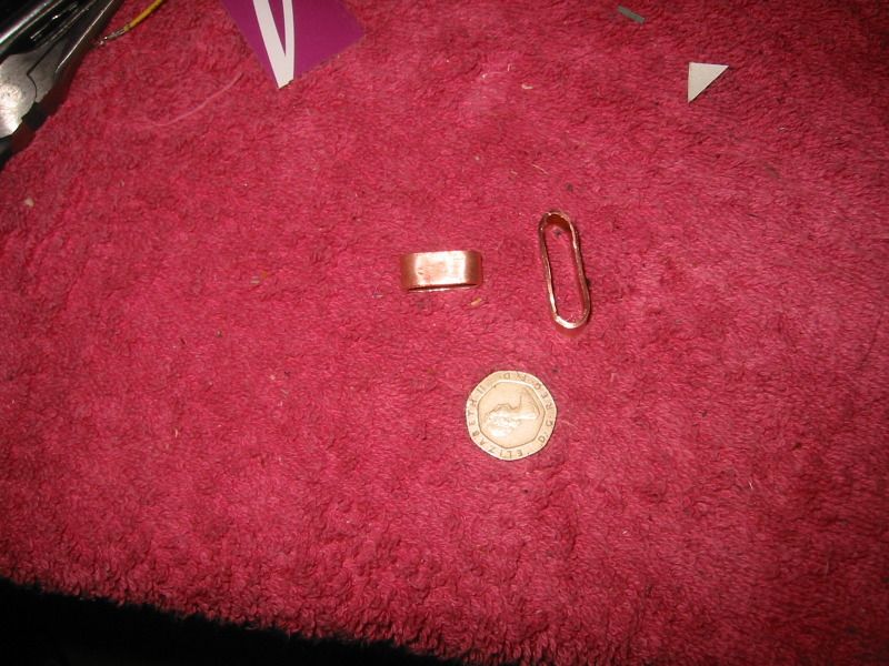
 
The transistors can probably run passive at less than 0.5A load and the those little heatsinks I made out of a picture hook was perfectly adequate even when heatshrunk. I was just looking at other options. I could even make a compound heatsink out of two or three of them, and I can get dozens of them for £1.

I wonder though if I could splay out the aluminium to reduce the height a bit. I think I will need to use a bolt and nut to hold these things on as those little thermal tapes aren't really strong and would probably come off under the heatshrink.

Thanks for the link Resident. Those do look nice and are low profile. At 36p each though it's pushing the cost up a considerable amount for something that's never seen.
 
All true.

I could make a batch out of 18mm copper tubing... cut of rings 6-10mm and press into oval shape about 6-8mm high. ;) Would that work?
 
Hey that's a great idea Doyll. Copper is a better conductor than brass and is easily solderable. It would need a flatish bottom where it makes contact but apart from that it can be curved.

Want to try that. I'm wondering if I have a section of copper plumbing tubing down the shed.
 
Will have to use a ruler to determine which would be best fit, although I'm leaning towards the bigger one. There's plenty of board space, it's just the height which is the issue. Any package over 25mm thickness costs a lot more to send.
 
I could just cut a handful of each and post them. You could bend them to your heart's desire. ;) All I really need to know is how wide to cut them 8-9mm is width of roller in cutter so easy to gauge... so is 13mm width. ;)
 
Just grabbed an old circuit and checked 30mm length is absolutely fine, 9mm height is ok I think and as for width 13mm will be great. Should really help with heat dissipation.

The thickness may not be much but it's probably more than the thin picture hooks.

It's always the ghetto ideas that are the best isn't it. :)

Thanks mate.
 
Email me your info and I'll post you some. Hope they don't get too mangled in padded envelope LOL

Edit: Threw a handful your way. Should hit to in a day or two :)
 
Last edited:
Thanks mate..

Guess what?

They arrived while I was at work today.

P1050446.jpg


Will slap one on over the coming days (training tonight so no time) and see what sort of effect they have, although I may have to flatten them a little more.

I should be building another one for forum member Casterina soon (for 2x SP120s) so that one will be the first to use official 'Doyll heatsinks' :)
 
Last edited:
:o You didn't need to embarrass me with those fugly things. :rolleyes:
I cut quick with tubing cutter, cleaned out inside burr, dressed ends,stretched/mashed to that shape and cleaned with some vinegar and salt so hopefully they would be easier to solder. Maybe an hour playing around.

Cleanest are the last few I did.

I didn't flatten them. :eek: Sides won't stay straight and flat.

I used a shot filled plastic hammer, 2 screw drivers inside of tube and a hardwood wedge driven between the screwdriver shanks to spread them. :D
 
Back
Top Bottom