Random 3D printing chatter

I use dumb toolboards for the extruders on my iDEX and they use ribbon cable, no issues with the hotend. Take a look at Jon channel he did a couple of videos on custom connectors/quick connectors. Like this one

Cheers Bulb, that's interesting. I was more excited by the 36W4 connection....until I checked and it's £20 for the female version (with solder bucket pins) and they don't even do the male version. Might have a browse round and see if anyone else does them. Either that or I have to buy an MLSA printer! :D
 
Spotted some BasicFil for £7-odd for a ½kg spool. A spool of orange (like hazard warning ORANGE!) and one of red turned up this morning. My 9yo son immediately started bouncing up and down and making repeated excited strangled shouts of "Penguin!". He's very happy and had been hassling me all morning about slicing this damn penguin. He's wanted one ever since the demo cat (which has been named Chairman Meow! :rolleyes:) rolled off the printer as a first print. I told him I wasn't spending £22 on a spool of orange just so he could have a penguin! ....but £7 ain't so bad. So in true rod-for-my-own-back style, we now have parts in black, white, orange and red queued to print.

So far so good with the first of the BasicFil. Bit stringy....but that's my extruder setup. Fed very nicely into the tube - much smoother than anything previous. So much so that I took some calipers to it to check it wasn't undersized! Measured 1.74 - 1.75 so I think it's just smoother.
 
Today I installed the Duet3D 3HC Expansion Board which meant I needed a custom acrylic mounting plate and as I only had clear acrylic I replaced the 6HC mainboard plate too. Bit of logo engraving too and I'm really happy with it. Now I have multiple independent Z motors so I can adjust for bed tilt. Purchased from Ooznest.


Very nice. What's the ribbon cable between the Pi and the Duet? Presumably it's connectivity from the GPIO pins to the Duet but what sort? I'm used to a USB connection....but then that's only a carrier for serial I suppose.
What are the 6P6C connectors (RJ11?) too? Interconnects of some kind?
 
Very nice. What's the ribbon cable between the Pi and the Duet? Presumably it's connectivity from the GPIO pins to the Duet but what sort? I'm used to a USB connection....but then that's only a carrier for serial I suppose.
What are the 6P6C connectors (RJ11?) too? Interconnects of some kind?

The duet is running in SBC mode, basically the network/DWC is running on the Pi leaving the duet free for only printer processing.

The RJ11 is the CAN bus connection between the 6HC and 3HC, I could chain expansion boards and/or duet Toolboards.
 
You've heard the phrase "When all you have is a hammer, every problem looks like a nail"? You'll soon find you've just got a different-shaped hammer! The problem is in knowing when NOT to use the 3D printer. Decorative items, things to keep your kid happy for five seconds, small enclosures for electronics, prototypes. Not forgetting, of course, upgrades and stuff for the printer itself....that's always a priority!
 
Hours of grief! You want to find out how close the tolerances need to be and how far off the mark you printer is, try printing two Lego bricks and seeing if they fit together and stay together!
Exactly - hours of fun, you'll not have any time to figure out what to print next as you'll keep on printing bricks!
 
Hours of grief! You want to find out how close the tolerances need to be and how far off the mark you printer is, try printing two Lego bricks and seeing if they fit together and stay together!

:D :D - So true... mine is an absolute dream now, every time I tear it down and rebuild it it gets a tiny bit better each time.
 
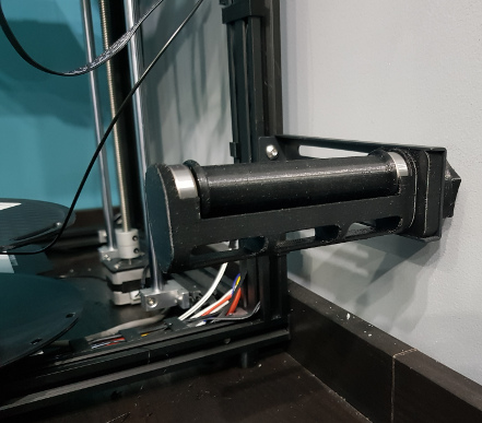
This is fitted with the supports removed. The arm it's mounted to is the Ender 5's factory arm. The square part of my model lets you mount it like this or on top of the printer once I've got a direct extruder set up.


At the risk of talking to myself, I thought I'd update. When I made this I simply modelled some holes in each end of the part and then ran a reamer through them and made some stub shafts out of aluminium to take the bearings. I wasn't careful enough making sure I reamed the holes concentric to the part so the stub shafts weren't perfectly inline with the roller. That means that as the roller rotated the distance between the top edges of the bearings got longer and shorter. There wasn't any space in the holder for that so mostly the spool just slid round the spindle rather than the spindle rotating in the bearings. I reprinted the spindle with a 12mm through-hole down the centre and then reamed it to size (holes come out undersize on my printer currently) with a cheap import reamer - not really sharp enough when compared to the smaller ones I have that are of decent quality. Made a full length shaft that was around 12mm in the middle (had taper issues with my lathe at the time) and had 8mm diameter ends for the bearings. Used my swing press (that's an overly fancy term for a hammer when you don't have the right equipment to press it in properly) to push the shaft into the spindle, set the bearings on the end and now it turns quite nicely.
When I printed the 1st replacement spindle, there were several lines in the print that didn't look right and I thought they looked like weak points....snap....I was right. I think it was caused by the fact that on this spindle the very end of the filament sticks through a hole (to retain it) into the centre of the spindle. Better ones have this go into a space that isn't right in the middle where the spool spins about. This got hung up on the arm because it didn't have a spindle in it and I think meant that each layer that came about when the tail of the filament got stuck on the holder, under extruded enough that there was no strength there. 2nd one was better (with the old spindle back in place) but didn't look perfect. Wasn't sure it was going to survive the reaming to be honest - sharper reamer would have been a lot better.


That's interesting.

I have always wanted a motorized spool spindle.
 
There's a few models on Thingiverse (search "rewind spool") that will do auto-rewind with basically a clock spring and a clutch. Not sure how reliable they are though from the comments.
There's also some very similar to my one that I took inspiration from and that lets you print the 8mm pin in one end of the spindle as part of the spindle and the other end as an insertable part - so you can stand the spindle upright on a flat end to print. My printer isn't (currently) accurate enough to get away with that. It's also worth mentioning that cheap skateboard bearings don't free-spin very much. There's a bit of drag either from grease or perhaps just because they're cheap, not sure which.


I found a motorized version.
But no one stocks it anymore. It's called The monster feed Pro
 
Back
Top Bottom