Robocain - Robocop 2 robot

forgot these photos yesterday

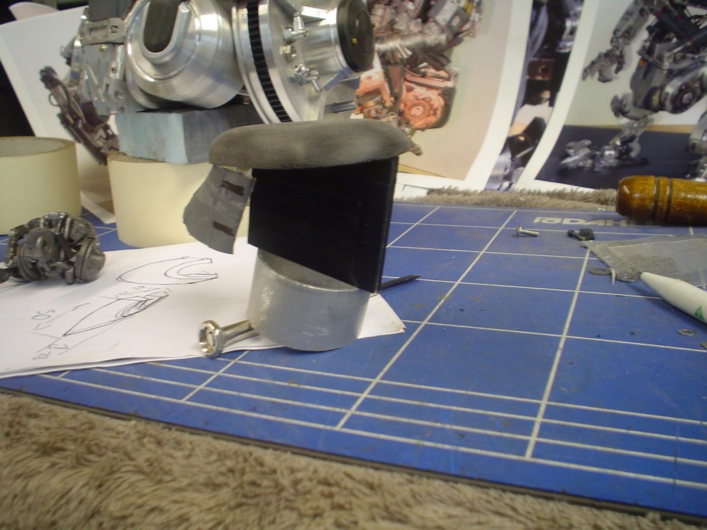
DSC09262.JPG


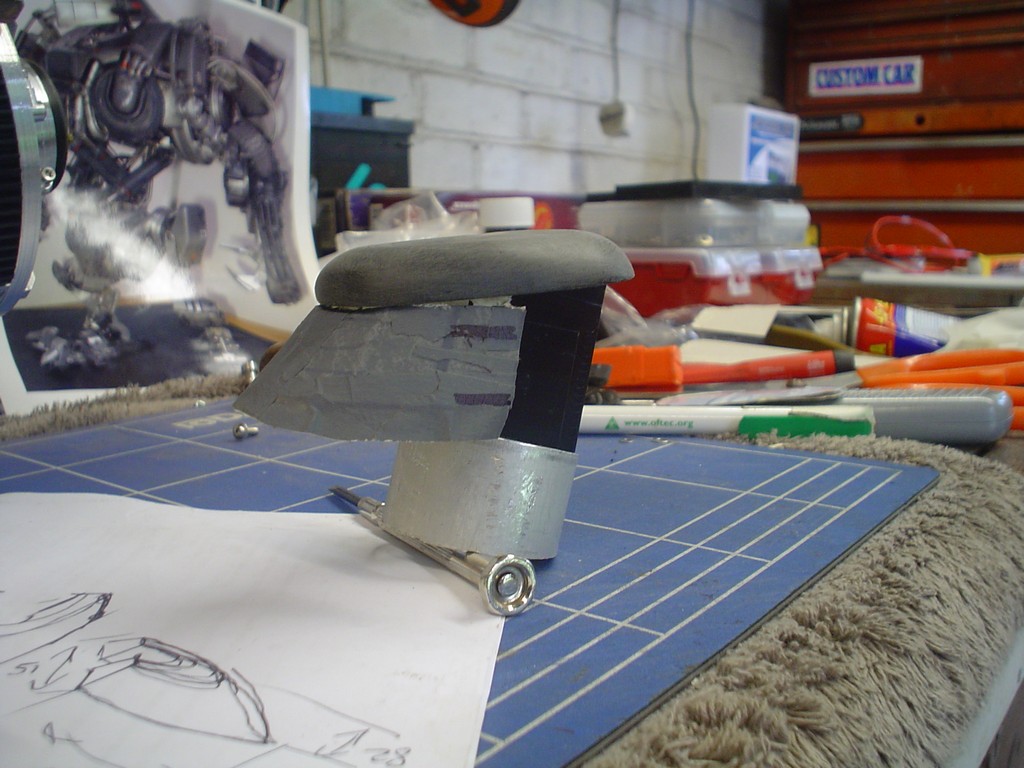
not sure if this is sloped enough

DSC09263.JPG


Im leaving that for a bit so I can think some more

need to make a plate at the back to mount everything on

DSC09264.JPG


very hard to get this right, the holes at the back where the head hydraulic cylinders mount have to be ............ in the right place...... I know what im going on about.
DSC09265.JPG


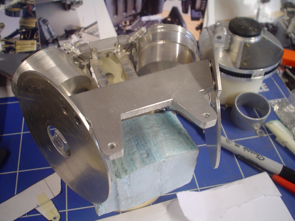
fitted up and it clears the chest, made some U brackets
DSC09266.JPG


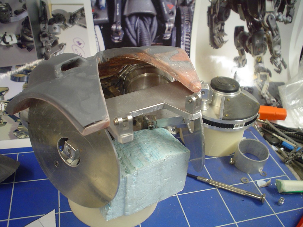
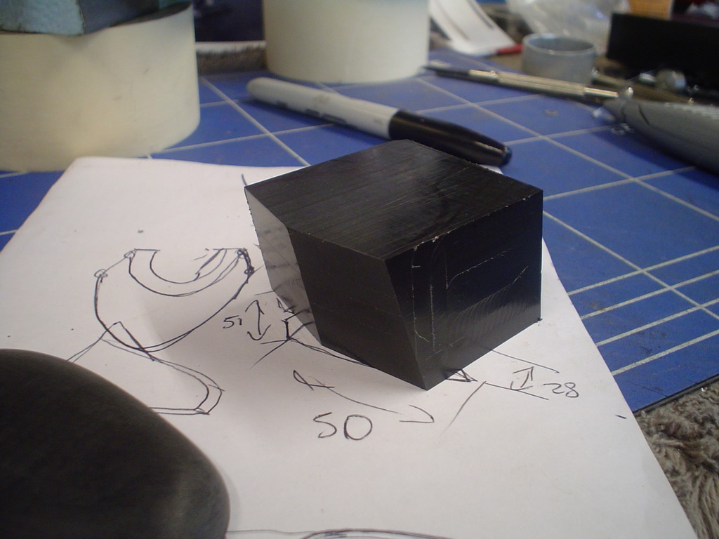
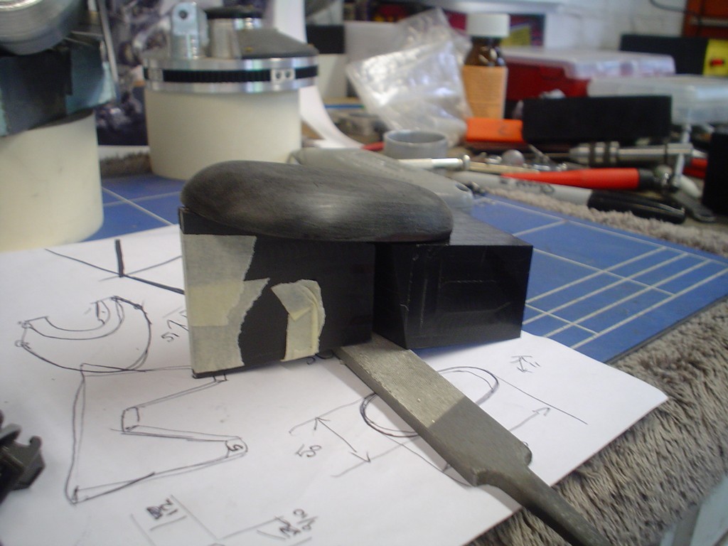
ok back to the stupid head thing, this has to cut the same each side (obviously) so it has a few degrees tilted to the side and a few tilted back at the same time, this is not easy to co-ordinate........... especially when your making it up as you go along
DSC09267.JPG


DSC09268.JPG


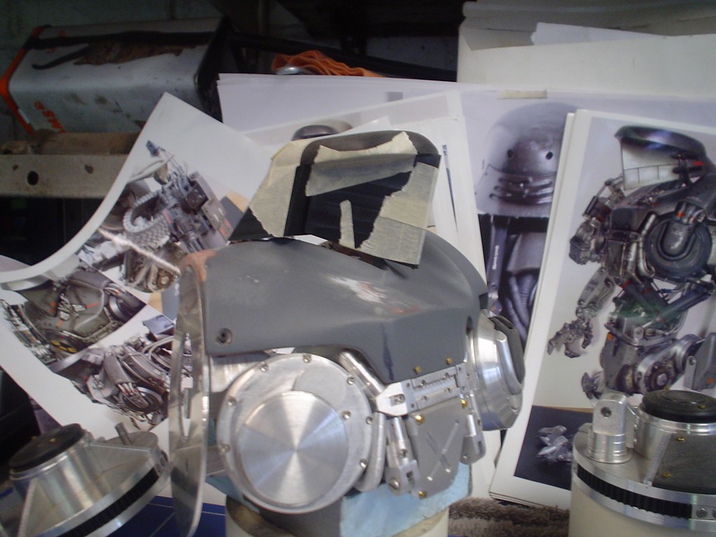
looks like he cut himself shaving, so the back of the head slopes to far down, need to trim that, but then....... its gonna be too short, might have to start again on this.
DSC09269.JPG
 
While I go some of the angles right it does tip back too far

DSC09270.JPG


DSC09271.JPG


I haven't got another piece of delrin big enough so im going to have to come back to this.

I keep finding parts I forgot to make, this is one of them

DSC09274.JPG


DSC09275.JPG


DSC09276.JPG


DSC09277.JPG


Also made up a removable plate

DSC09278.JPG


and another little plate that sits up high by the front of the collar.

DSC09279.JPG
 
made some more little fittings

DSC09280.JPG


this is the little plate at the front of the collar, im not sticking too strictly to the real one here, close enough.

DSC09281.JPG


these are the catches that hold the head locked dpwn when its in park. They are rather fiddly!

DSC09285.JPG


tiny tiny

DSC09286.JPG


they will attach up here somewhere

DSC09287.JPG


DSC09288.JPG


Turning some large nuts down to make the big pipe fittings at the top

DSC09289.JPG


DSC09297.JPG


using some of the micro hex head screws, half a mm thread width

DSC09298.JPG


DSC09300.JPG


DSC09302.JPG


DSC09303.JPG
 
Yes, at one stage I think I had dropped so many bits on the floor it would have been easier to start working down there.

Just a mixture of tube, rod, threaded rod, nuts etc to make up the fittings, when painted they should look correct.

DSC09304.JPG


DSC09305.JPG


DSC09306.JPG


DSC09307.JPG


DSC09308.JPG
 
Made up one of the armour plates for the back, the other side doesnt have one in the pictures but I will probably make another for that side, it looks like it needs one.

DSC09315.JPG


metal plate for the back

DSC09319.JPG


where I have spent a great deal of this year, sitting staring at a picture with a slightly stupid look.

DSC09320.JPG


recesses cut and thinned out a bit

DSC09322.JPG


rubbed down and holes drilled for tiny hex head bolts, just about spot on i think

DSC09324.JPG
 
Its ok, as the weather turns bad I spend more time working on it. In the summer I spend most evenings out but now its time to get down to it!

Got a new chunk of delrin a last, im using the other as a template

DSC09333.JPG


cut the sides, this is hard as there is 2 angles to worry about and both sides have to be the same.

DSC09334.JPG


using my nifty vice, I can pivot to the correct angle then use my bevel box to twist it in the jaws to get the other angle, make a not of them, then repeat for the other side.

DSC09335.JPG


much bigger slant to start with, some of it will be lost when i trim the bottom.

DSC09336.JPG


its a good start

DSC09337.JPG
 
Originally I was going to open up a cheap chinese MP4 player for the screen

chinamp4.jpg


however after looking at this a bit closer the screen will have to be some distance from the board that controls it due to the complex movement the screen will have to do. The pitch of the cable is very fine and trying to solder an extended version on is a bit of a pain. So I have been hunting on the web for a solution, most of the tft screens of about 1.6/7/8 inches have to have a board with them, plus a video source as well, not only that but they are backlit and so quite thick. Finally after hours of searching I have found an Organic display (OLED) that should do the job, no back light and the whole unit is only 6mm thick which I should just be able to pull off. The other downside to the MP4 player is when you turn it on you would have to navigate through the menu to the video, with this module I have bought it can be set to auto play a file as soon as power is applied. Only down side is its a development module and so I might have to learn a bit of programming to actually get the thing to work, oh yeh ands its nearly £90 :(. If anyone is interested its coming from 4D systems in Australia.

Made up some brackets for the head doors, also trimmed the doors down on the inside to give me some more room.

DSC09339.JPG


Im using an old battery as a mock screen, its more or less the correct size! I made a aluminium bracket thing and a brass rod with a little plate on the end thats hinged.

DSC09340.JPG


The idea is the screen will twist sideways and slide into the head and the doors close.

Had to carefully remove material from the inside of the head.

DSC09341.JPG


Got the doors in and drilled in the right place, they hinge ok, but still a bit of resistance, some screws inside are there to adjust where the doors close so they meet in the middle.

adding a tiny spring to pull the doors closed.

DSC09343.JPG


im just hitting this head on at the moment, not 100% how im going to get it to open the doors, screen out, twist and the reverse the whole sequence at the push of a button but im sure I can manage it somehow.
 
Spent a long time on this but finally got the basic mechanism in and lined up. The doors now meet in the middle consistantly.

DSC09344.JPG


DSC09345.JPG


Then if you pull the doors open and tug on the "screen" and twist, it opens in the right place! I had to carefully trim away material inside to get the screen in and the doors shut, it has to pull back a long way into the head to give enough clearance. Not only that but the back corner of the screen protrudes above the line of the doors so the lid of his head will have to be scooped out a bit too.

DSC09346.JPG


The brass bar that the screen is on slides back and there is just enough head to cover it, its all a bit tight. Now the fun bit, getting it to open and close automatically. I played with a few ideas, boiled down to 2, 1st was to have a screw/ worm drive to move the slider in and out, but for this the screw would have to extend the length of the rod and there is no room. So had to go for option 2, a cable inside a tube..... like the brake cables on a bike. I found a suitable tube, rc car antenna pipe, with a bit of heat they bend and stay in shapes. For the wire I got a reel of wire and found that 3 strands twisted together gave the best trade off between strength and flexibility.

DSC09347.JPG


After yet more hours of faffing about I came to the conclusion that having the doors srung shut is not going to work :( the force needed to open them is quite high, this needs to be done by the screen twisting 90 degrees open at the end of its travel on the brass rod. However im going to push from near the pivot point, it needs a huge amount of force to lever the doors open which isnt going to work, the cable (doing the pushing) will bend.... use thicker cable? cant it needs to make a 90 bend from the body up, turn then out to the screen. SOOOOO im thinking I need this U shape bit that I will mount the door springs to....... then when its pulled back the doors close AND have tension on them, but pushed forward the doors are free to open. I just need to somehow get the cable to open the doors THEN push the screen out all the way.

Did that make any sense? prolly not, in short, this is a ball ache.

DSC09348.JPG
 
ok ok settle down chaps, plenty of time for me to get naked later.

I think i got it,

So cut this piece down quite a bit as the screen kept catching on it (so little room in here) attached the sprngs to the front of the U.

DSC09349.JPG


A lot of work in here, lot of trial and error. The screw on the end of the brass bar stops the bar going to far. The little screw up by the screen end just clears the 2 on the bracket (holding the bar in place) when the screen is retracted it passes them then catches the recess in the U shaped piece, pulling it back. Then when the brass bar is all the way back it meets the back of the head where the cut out is and the U shaped bit is pulled back against the head. This is enough to pull the doors shut with a little tension on them.

DSC09350.JPG


Just bellow where the brass rod is there is a hole that I can fit the tube...

DSC09351.JPG


like so, had to trim the U piece even more as it'd catch on the tube. The wire feeds out and attaches to the pivot on the end of the brass rod. As the wire feeds out it pushes the brass rod out, then it extends fully it pushes on the pivot and flips open.

Bottom line is it kinda works, just need to refine a little more then i'll get a video up.
 
Thanks for the support chaps.

The original puppet had a lot of plastic parts, a lot of the arms were plastic so they only had to make one then make a mold, easier that way as they needed a lot of them. No idea how long they spent on it though.

Should be pretty much wrapped up by christmas, getting the head mechanism to work was the last big hurdle, so all down hill from here!
 
Yes thats right, no real models of this to speak of due to the complexity.

Little 2 inch tall model by koto somebody, not bad, its in some of my photos, for scale its a bit naff, the feet are HUGE but it looks ok. There was a kit by argonauts, 1/12 scale that you had to build and paint but this was fairly in accurate, still a good base if you wanted to spend some time on it making it right, adding all the pipes and stuff.

I like making one off's, things that you cant buy else where. The guns I made at the time were of models of gun that couldnt be bought, the WA2000 was quite rare and the only one I could find was £2000! Just seemed like the cheaper option. I would get bored making another Cain or even making molds of it, as you can imagine im getting pretty sick of the sight of it now!
 
moving onto the other end of the cable, gong to make a sort of worm drive to move the wire up and down

DSC09354.JPG


got me a little motor and a pully from somewhere. Motor turns the big pully which is on the thread/screw. The lump of metal on the right has a thread tapped in it and is stopped from spinning round by the 2 poles, it has no alternative than to move up and down the thread.

DSC09355.JPG


had to do some more work on the colar to get it to meet the head flush, even though it'll be lifted off the collar.


DSC09356.JPG


DSC09357.JPG


in place and nearly working, had to modify again, needed a lot more tension on the rubber band thing. It was a bit loose, lost traction and spun, the pulley on the motor got so hot it melted! so now made a lottle alloy pully you can just see it, good huh? :)

DSC09358.JPG
 
Yeh its good stuff, very rigid, you can machine it like metal.

I took the head apart and started to rub down all the rough edges and smooth the surface out, taking out all the machining marks.

DSC09360.JPG


DSC09361.JPG


test fitted to the torso, started to turn the cylinders for teh back of the head, im going to fit them as close to the head as I can.

DSC09367.JPG


and drum roll please! I got my screen! This is the OLED (organic LED) from Australia, took me hours to get to grips with the software and finally get a proper image on the screen, now I know it works I can get on with editing a longer sequence and editing the colours down a bit. I know this looks a little odd but its good for a trial run!

DSC09368.JPG


hey cain, whats happening!

DSC09369.JPG
 
Thank you all for the kind words and support, keeps me going really :)

So impressed by this thread, you really do have a talent there. Out of interest (and aplogies if already asked in this thread) but have you contacted any of the original modelling team. I'm sure they would be interested in your work.

Yes a chap in the robocop forum (yes there is one lol) works at Tippet studios, the main man, Phil Tippet said "he's mad" make of that what you will.

holy good gravy, that's incredible!

how are you powering the OLED screen? does it have it's own driver to go with the other control circuitry?

Its a good device for my needs, had to program it with 4d systems own software but got the hang of it now, I have shorted the jumper on the back which means it'll auto play as soon as power in connected. I will have to run power to it, i'll get some thin wire so it doesnt hook up on the mechanism.

Had to re mount the plate in the collar since re-shaping the collar.

DSC09371.JPG


mounted more securly now with a proper joint so I can adjust the head, also finished and mounted the head hydraulics, considering they attach to the bottom of the head ather than inside the head I think they look good!

DSC09372.JPG


you can just see the front cylinders here, they should be more promanent but with the screen moving in and out here its just not possible so this is as far forward as they can come.

DSC09373.JPG


made another armour plate for the back of the neck

DSC09400.JPG


Onto a job I was putting off, having to cut the grooves in the head for detail, this was done with a hacksaw blade and a razor blade (no really)

DSC09401.JPG


DSC09402.JPG


DSC09403.JPG


looks a bit more real now

DSC09404.JPG
 
head back together and mounted up

DSC09405.JPG


remaking the screw drive for the head, old plate on the left new in the middle.

DSC09422.JPG


I wanted to mount the unit sideways in the middle of the chest but for this the cable had to do a 90 degree turn out of the screw drive and then another 90 in the head, this was too much the wire would kink. So I have to have it pointing straight up into the head, not a big deal, it'll stop the inside of it looking empty, its tucked away out of view from the front.

DSC09423.JPG


somthing else I missed before, slotting this part of the shoulder back plate.

DSC09426.JPG
 
Back
Top Bottom