Ronski's Solar & battery DIY build with whole house backup

Soldato
OP
Joined
3 Dec 2012
Posts
3,643
Location
Kent, much sunnier than Scotland
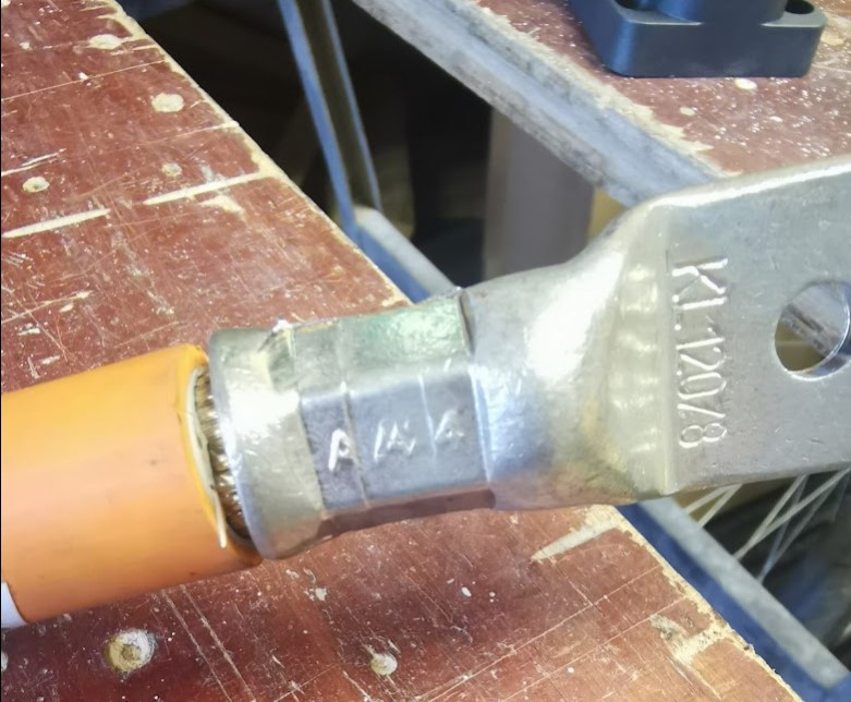
Tried the new crimper today, it makes light work of crimping, but it is really heavy and cumbersome to hold, but it does beautiful crimps, crimped this one twice just to get a slightly longer crimp. With the other one you have to crimp multiple times, rotating the lug to get a nice crimp.

120-Crimp.jpg


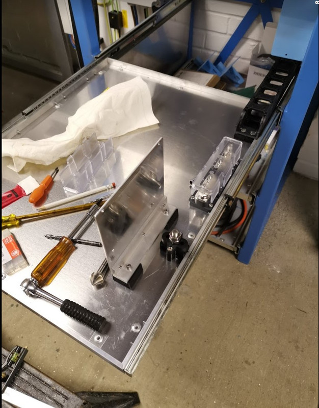
Started building up the second battery tray, cell's aren't arriving until late April, but there is plenty to do.

Start-of-Battery-B.jpg


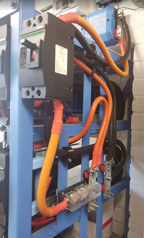
And also the main rack fuse and busbar.
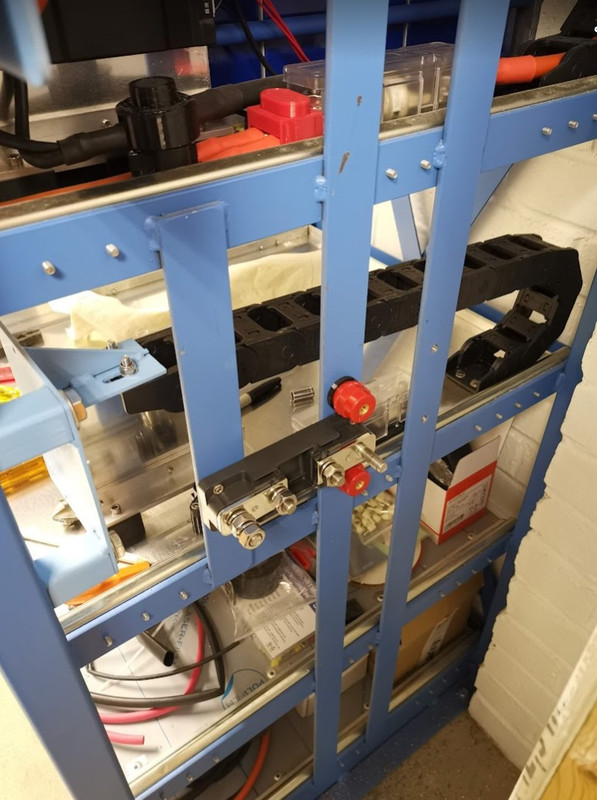
Rack-Busbar.jpg
 
Soldato
OP
Joined
3 Dec 2012
Posts
3,643
Location
Kent, much sunnier than Scotland
The cables from the main rack breaker are 120mm, which I realised yesterday posed a bit of problem, as the lugs I had were straight, which meant the cables would come above the top of the rack. All the angled terminals I could find online were too wide for the breaker.

So I put them in the vice, between some aluminium so the faces weren't damaged, and carefully bent them, I now have angled lugs :D

Bent-Lugs.jpg


I've been designing some 3D printed covers to go on the moulded breakers, amongst other jobs I had to do today, so not much done on the battery system.
 
Last edited:
Soldato
OP
Joined
3 Dec 2012
Posts
3,643
Location
Kent, much sunnier than Scotland
Last week I made some terminal covers for the main breakers.

Breaker-Termianl-Covers.jpg


The easy way to get holes in the correct place, print out a template.

Busbar-Template.jpg


Fitted two more breakers, the busbars and made up some more cables, 120mm cables from busbar to main breaker, 70mm cables from busbar to second battery breaker, and got the positive cable down to the battery tray fuse.

Rack-Busbar-and-Cables.jpg
 
Last edited:
Soldato
OP
Joined
3 Dec 2012
Posts
3,643
Location
Kent, much sunnier than Scotland
Today I conducted a SolarEdge Inverter automated shut down test, basically if the grid fails (so we're running off grid) the system needs to reduce power when the batteries are full and solar production exceeds demands, if it doesn't then the batteries are used as a soak until the BMS cuts off due to exceeding the maximum voltage, at that point the inverter will shut down.

Unfortunately I was busy packing a parcel and wasn't keeping an eye on the state of charge, and it had got to 99%, the solar was generating circa 6kW, so I needed to drop the SOC to about 90%.

Washing machine was on, both ovens was on, kettle was, microwave was on, and I put the twin draw air fryer on, cue about 11kW of draw and minimal grid draw - just noise as the solar went up and down.

SE-Shut-Down-Test.jpg


Anyway I managed to get the battery down to 90% and after turning all the extra loads off apart from the washing machine I flicked off the grid supply.

Now I thought the system would close down the SE Inverter at 95% SOC charge (there doesn't appear to be a setting for this), but it didn't, it kept going, then the garage PV shut down at 99%, leaving the house system going, that shut down at 100% and the garage system came back on at a reduced output to cover loads.

So the experiment was successful and proves the system does what its supposed to.

2023-04-07-Strings-SE-Shut-down-test.jpg


2023-04-07-Strings-SE-Shut-down-tes-close-upt.jpg
 
Last edited:
Soldato
OP
Joined
3 Dec 2012
Posts
3,643
Location
Kent, much sunnier than Scotland
So when the battery full and grid down and you cant turn on your oven what happens. Where does the solar kW go ?

The turning on of the oven part was to drain the battery a bit, as I needed to verify what was supposed to happen, happened, which it did, and I wanted to watch it happen. Once the battery was down to 90% I turned off all the extra loads including the oven to allow the battery to charge.

When the grid is down, the battery is full, and there isn't enough AC load the Victron system will do two things:

  1. It will reduce the power generated by the MPPT charge controllers - it did this, you can see this in the last picture above, the red and blue lines are the two strings directly connected to the Victron system.
  2. The Quattro will increase the AC frequency to 52Hz (this setting can be changed), most (not all though) solar inverters will then shut down at this frequency, the SolarEdge inverter that I have shuts down at 51.6Hz - you can also see that it shut down in the picture above.
So you can see that the amount of power generated can be controlled, if the above two didn't happen then the power would be dumped into the batteries until the BMS turned them off to protect them from being overcharged, at that point as I understand it the Quattro would shut down.

Newer inverters can be set to gradually restrict their power, as the frequency rises above 50Hz they will reduce their output, the Victron can be set as required to control this.

ESS-Frequencies.jpg
 
Last edited:
Soldato
OP
Joined
3 Dec 2012
Posts
3,643
Location
Kent, much sunnier than Scotland
I've done some more to the second battery over the weekend, not a lot to show picture wise though, so no pictures. Made up the negative cable from the breaker down to the tray, made up a splitter for the T class fuse holder, made up the battery heat spreader, and did some other odds and ends.

I've also been modifying my scheduled discharge routine for Node Red, going to need this from tomorrow.

Schedule-Discharge-2023-04-10.jpg


The discharge timers are currently embedded in the flow, but its very easy to change them should I need to.

From the dashboard I can turn the schedule on or off, set how much battery power to discharge, and a minimum SOC of charge to stop discharging at.

It now takes into account AC loads and PV power, the aim being to set how much the batteries are discharging at - so the figure "Grid set point to use on the schedule" updates depending on PV production and house loads.
 
Soldato
OP
Joined
3 Dec 2012
Posts
3,643
Location
Kent, much sunnier than Scotland
Made up the last two 120mm cables and fitted them, the battery rack busbar is now live.

Need to print some covers for various parts, and also some cable clips, but I've stripped down my 3D printer hot end as it kept leaking, turns out the thread that the heat break screws in to has stripped, so when I tighten the nozzle it eventually pushes the heat break out a bit, and hence leaks again.

Once I get my printer working again, I'll print some cable clips just to tidy the cables up.

Battery-Rack-Busbar-Live.jpg
 
Last edited:
Soldato
OP
Joined
3 Dec 2012
Posts
3,643
Location
Kent, much sunnier than Scotland
Not much to update for the last couple of weekends.

Finished off and tidied up the rack busbar cabling, which is now all operational. Also cut and tapped the bars I use for connecting the balance leads, so they are ready. Bit of luck the new cells will arrive this week, I think I'm ready although bound to be something I haven't got or done.

Rack-Busbar-1.jpg


Designed and 3D printed a cover for the cable connections to the Lynx shunt

Lynx-Terminal-Cover.jpg


Designed and 3D printer busbar covers.

Rack-Busbar-2.jpg
 
Back
Top Bottom