Scratch build valve power amps

God I love this. Exactly the sort of project I'd have loved to get my teeth into once upon a time.

Great stuff OP
I'd like to say I've been enjoying it, but it has had the effect of making me feel just a tad thick at times. Trying to get my head around some of the theory has been very difficult. Between feedback compensation, phase shifts and poles my head pretty much fell off.

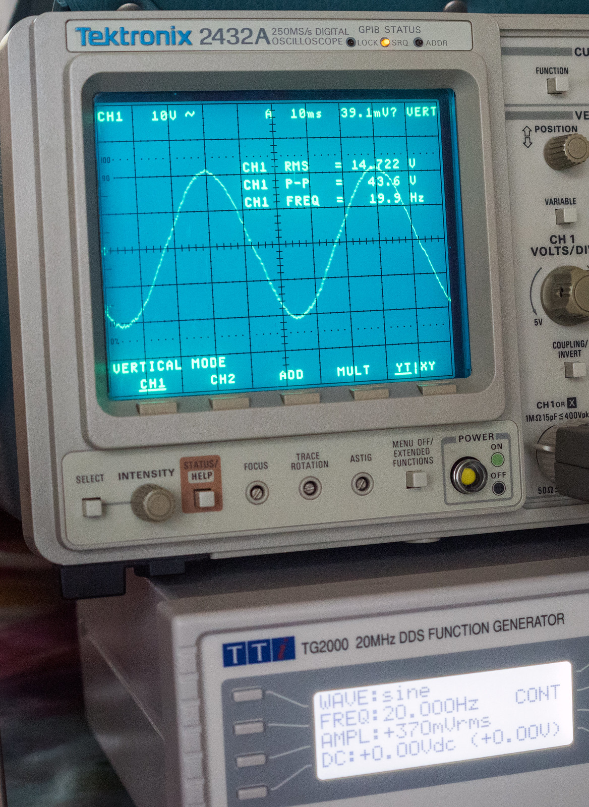
Made some more progress over the weekend. Modelled the transformer using just the signal generator through a 4.7K load across the anode connections linking the HT centre taps together and an 8R load on the secondary. Connected one channel of the scope to the primary and the other channel to the secondary and measured the time difference between the primary and secondary.
49960913223_607bea9748_h.jpg


Plotted the results on a graph

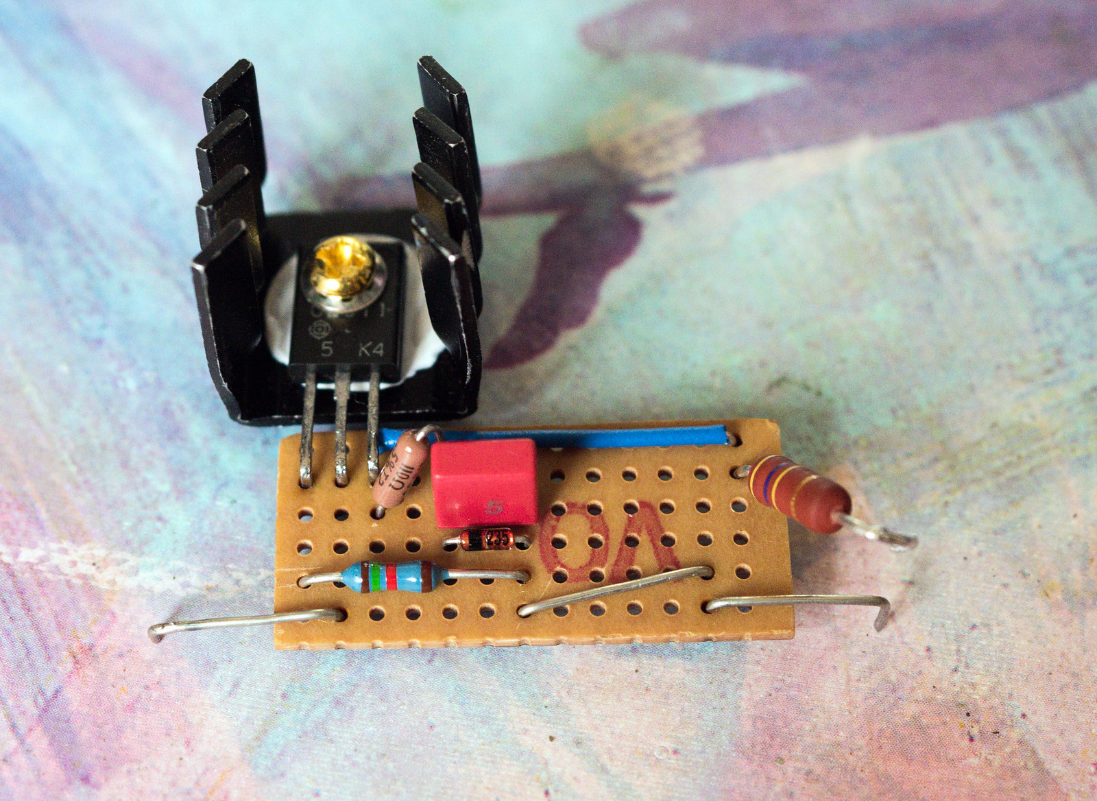
Got the constant current sink built on veroboard and fitted it to the main turret board.
49961358246_3d1ec18384_h.jpg


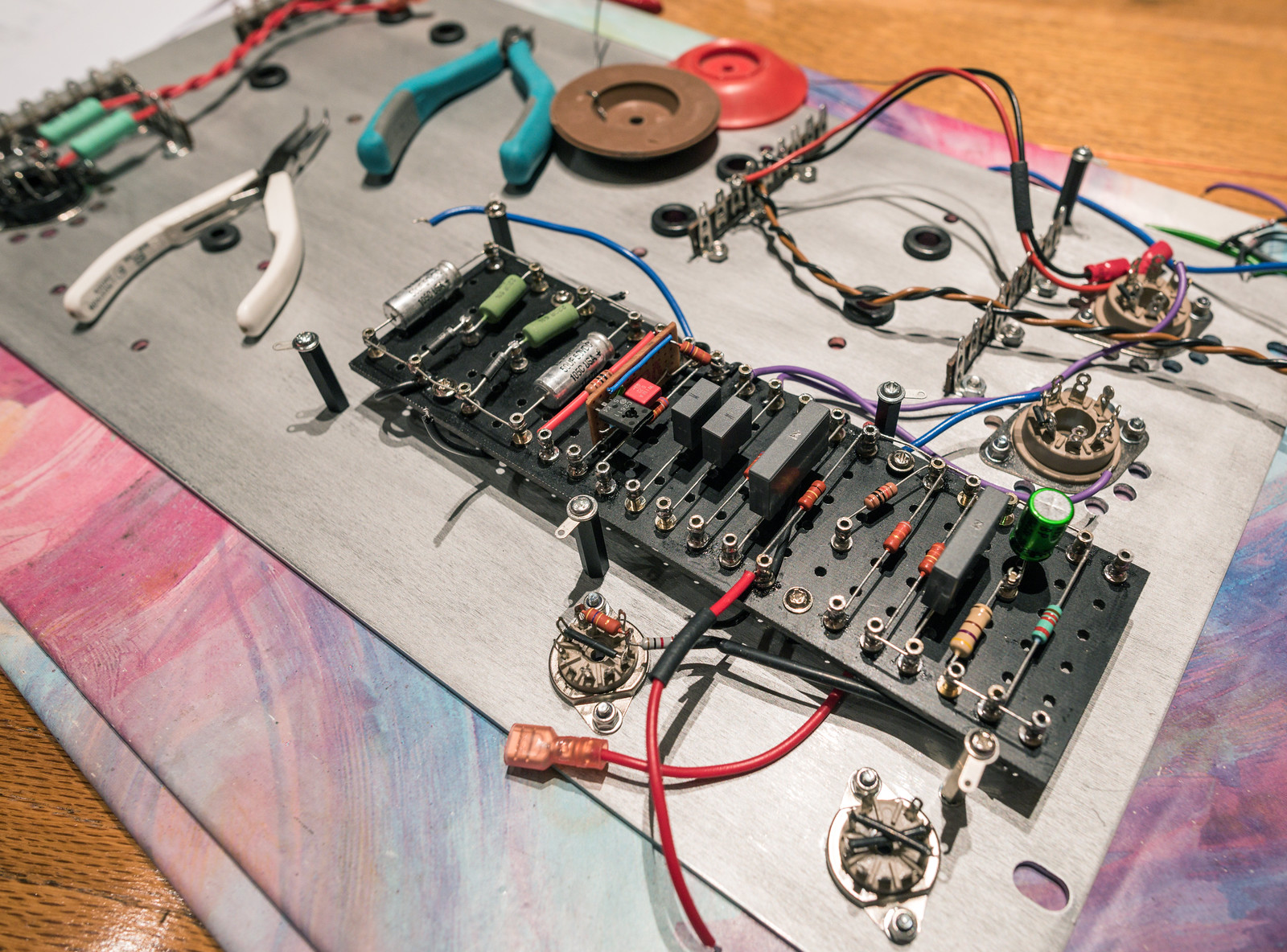
Finished off all but the feedback section of the turret board today.
49961641537_e4e3061554_h.jpg
 
Makes me quite glad I build guitar amps not hi-fi! There are plenty of imperfections and inefficiencies and downright "bad design" in guitar amps. It's what makes them sound unique and sound good. That said, my 18W push-pull EL84 amp is finished and it's too, TOO loud. Already planning out a more self-designed amp using just small pentodes for lower volume :o
18W out of EL84's is pretty decent. They are usually only 10W in ultralinear, but that is with the small power losses attributed to using cathode biasing. Most guitar amps don't seem to bother with negative feedback and those that do, don't seem to use much. This has been the massive brain ache I've been dealing with. The original mullard design utilised 30dB of negative feedback which for a valve amp utilising global negative feedback is massive. Most didn't exceed 20dB.

That's impressive. No idea what you're on about though! I always thought electronics looked interesting but aware it's a massive rabbit hole. Looks like you're learning a lot doing it, will be very satisfying when you finally get it completed. I'm just learning about basic construction, who knew there was so much to concrete :p Your project makes me feel mine is it actually quite easy, other than feeling like I've been run over every morning!
I certainly hope it'll satisfy once finished. It's certainly been a learning curve and far harder than I imagined it would be. At this stage, I feel I might have been better off just going to Audio Note and buying one of their kits, as it would have no doubt been easier but I'm starting to think, it may actually have been cheaper too.

Impressive build and great execution. I love DIY audio, something about scratch building is daunting to me though especially valve gear. I'm sure the sound will be exquisite and can't wait to see the final form.
The build quality on the side of my bodgetastic chassis builds may be a tad questionable, but the electronic side of it should be to a high standard. I'm still working on a way to build a decent metal chassis. I've been working on it every now and then since starting the third build as it had sapped my enthusiasm.

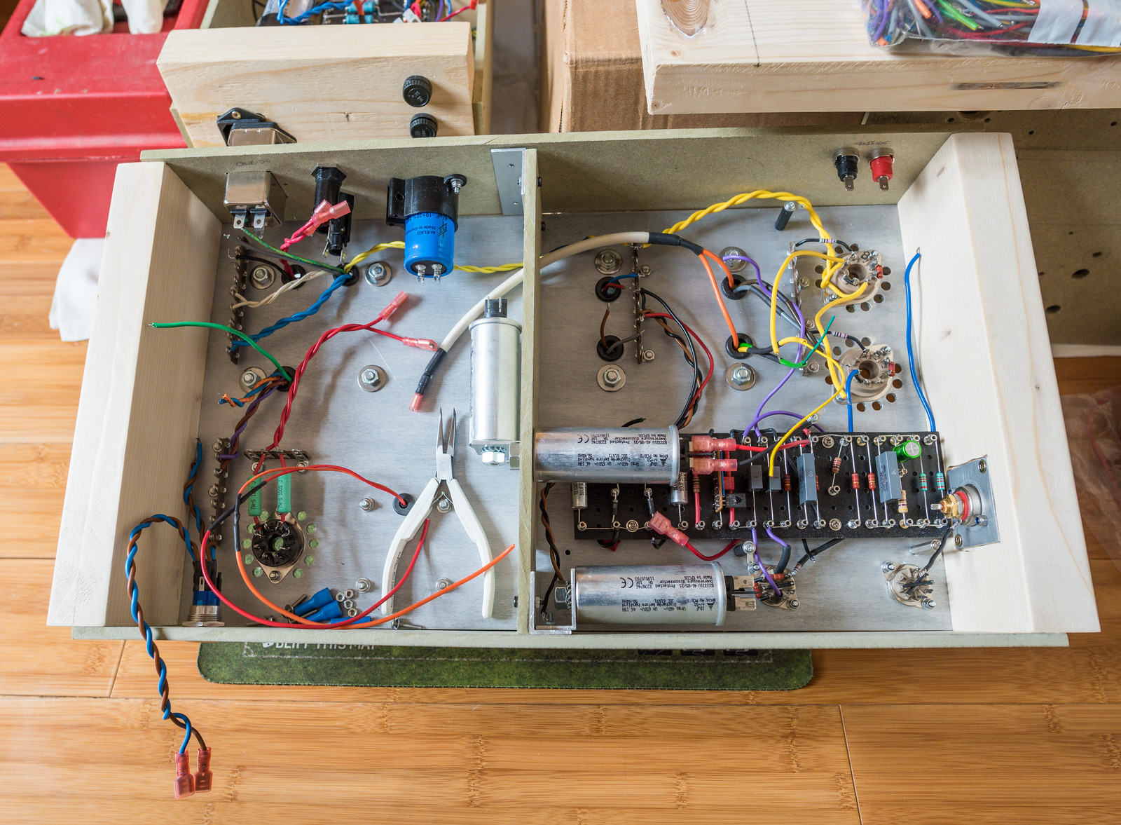
Currently, all the capacitors are now mounted in place and I'm battling with wiring it all back up. I had to extend some of the wiring that I cut off the transformers, which was not so fun.
50029051816_f5df52f795_h.jpg
 
Making slow progress, mostly as I'm doing bits for an hour or so every now and then. Finished the heater wiring and the power feeds. Got to sort out the grounding and the input. Thinking of using another piece of veroboard for the input components before the valve socket to allow for the use of shielded cable for the majority of the distance.
 
This is very close in style to what I was aiming for at the start. I still am aiming for this as the end result. If no one has noticed, the rather horrid MDF side panels actually have an error insofar as I cut them the same length as the aluminium top plate. Head not screwed on properly at the time, but it's not final so not really all that bothered.
50049750148_3cb8324412_o.jpg


I've drawn up a simple veroboard for the input to the first valve grid which will allow me to use shielded cable and keep things as close to the valve as possible. The twisted wire represents what will actually be single core screened cable.
50050283316_0db9891428_o.png
 
That's a sound idea. Certainly easier than making it completely myself.

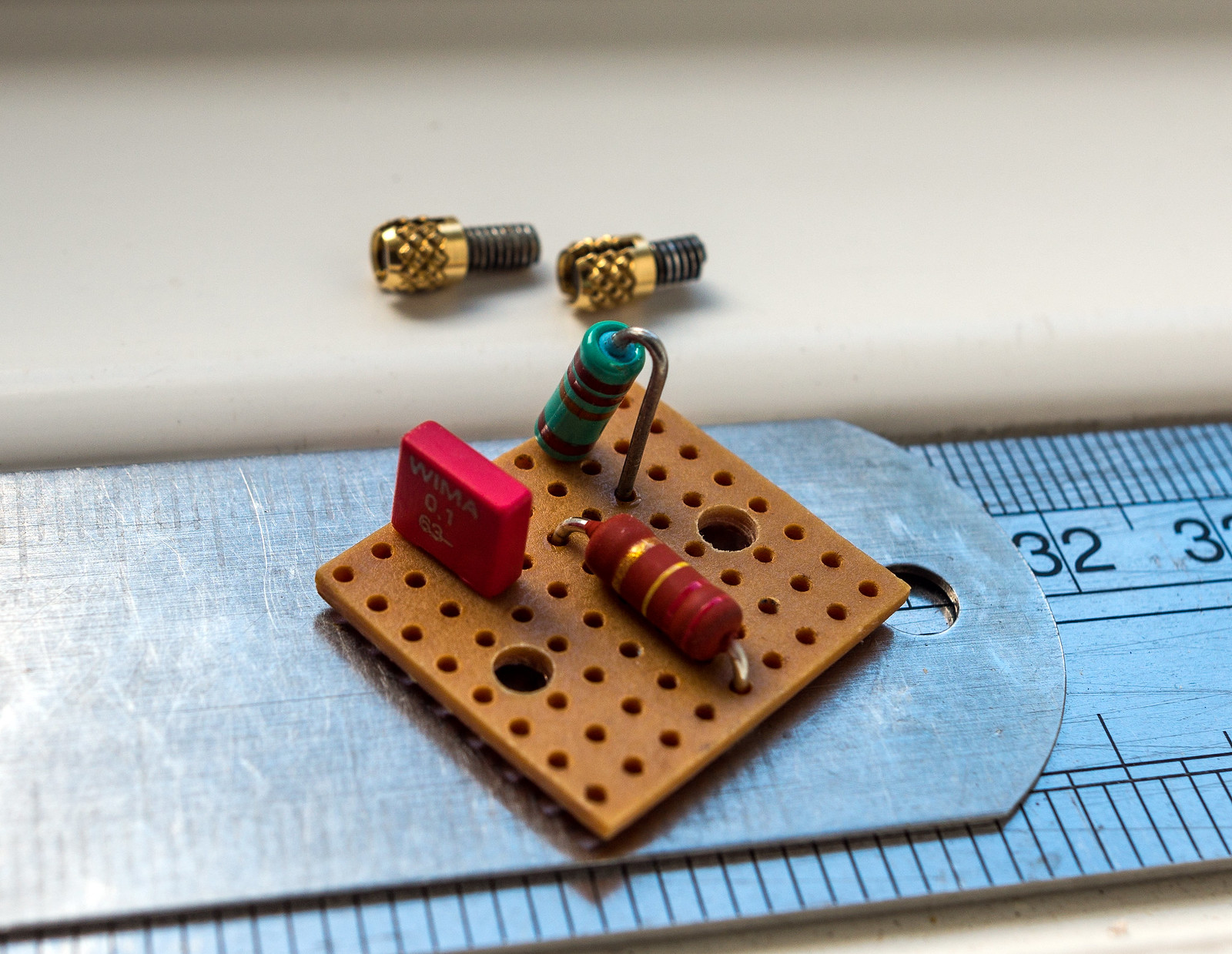
Finished the input board. Decided since I had some M3 threaded inserts, I'd give them a try. I had to make it a bit bigger than originally drawn as it turned out I had no low watt resistors.
50063325182_dacca2b2d1_h.jpg


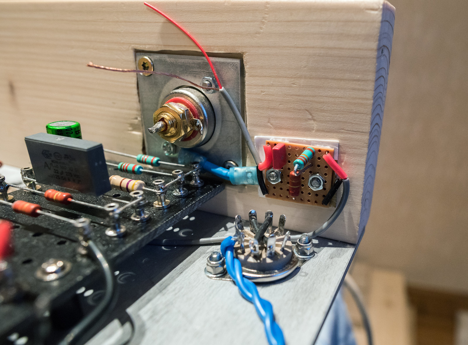
Mounted in the amp. I made a foil backed piece of card to act as a shield which I've grounded to the input socket plate. This will be linked to the ground bus. I also rotated the input valve by 180 degrees to make the control grid pin closest to the input to shorten the wiring.
50062509988_532a001b18_h.jpg


I've just got a little bit of wiring left to do before I can consider a test run.
 
Finally got the MK3 prototype finished. Should be able to do some testing once I've triple checked my wiring. Everything looks good so far.


I ended up having to rotate the CCS transistor in order to fit the heat sink. Thought it best to have one as it would need to dissipate ~400mW


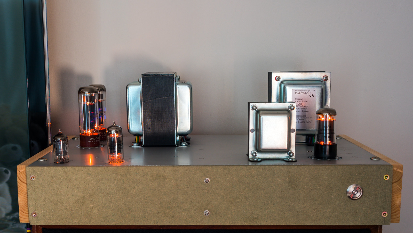
Decked out with valves, it definitely does look a lot better in aluminium. Just hope it performs.

 
Great project!
"ccs transistor" : ccs = ?? please.
CCS in this case meaning constant current source. The transistor is nothing special (2SC2611), CCS describes its purpose in this particular application. It's used in the cathodes of the phase splitter which sets the bias, due to its active nature, it also helps to balance both triodes in the valve. (so the push and pull halves are equal) The more traditional way of doing this is with a resistor but that is susceptible to drift as the voltage changes.
 
"Finally got the MK3 prototype finished. Should be able to do some testing once I've triple checked my wiring. Everything looks good so far."

Does it work??
I've still not got as far as testing it yet. I double checked my wiring and found a missing ground connection. I'm also double checking the component values for the biasing as I really don't want to muck that up and end up cremating a set of valves.
 
Got around to a test run today. No dramas thankfully, however there is clearly something not right as the phase splitter is not behaving correctly. The anode of EF86 looks great but the output of 6CG7 looks awful and notably, the anode voltage on 6CG7 is way over where it should be.

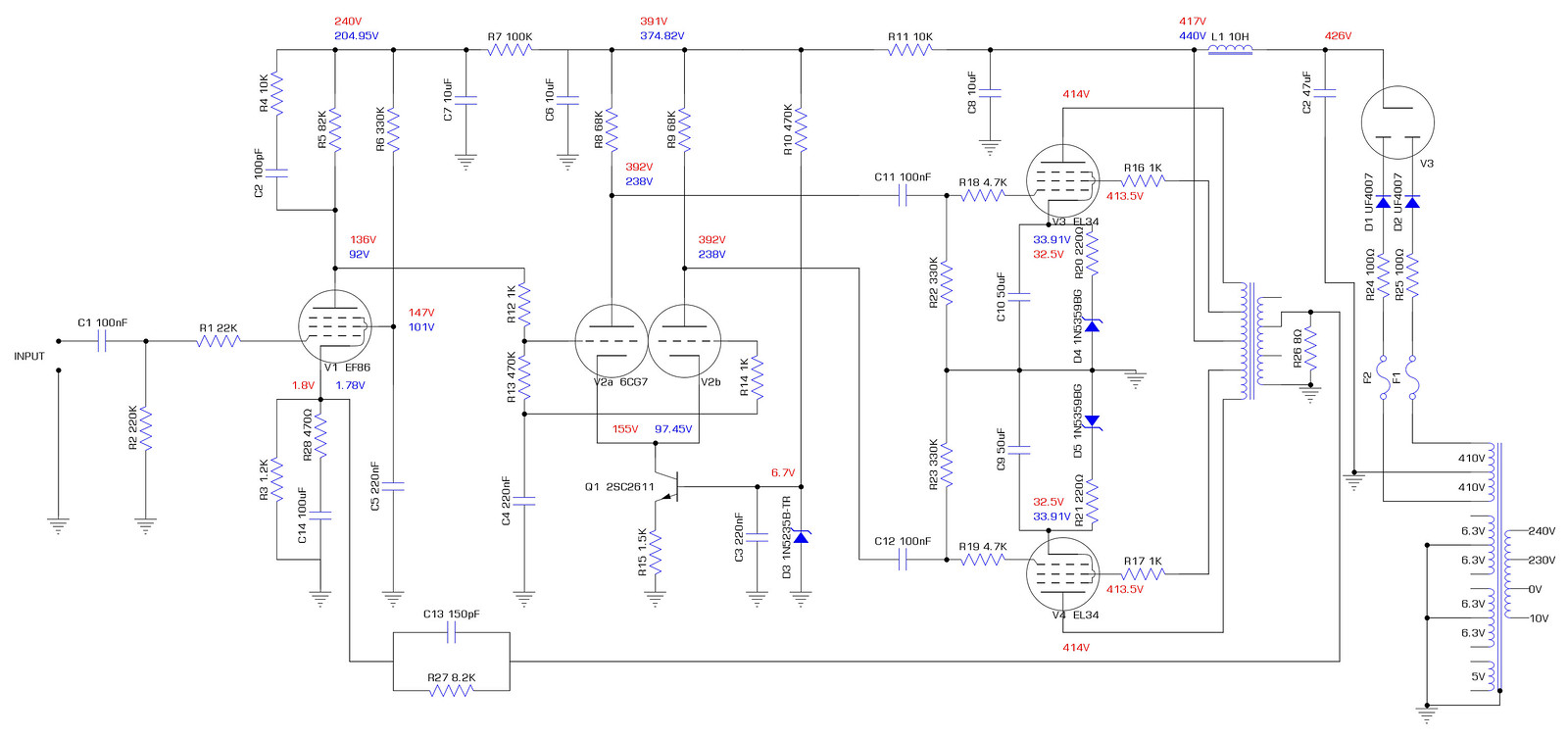
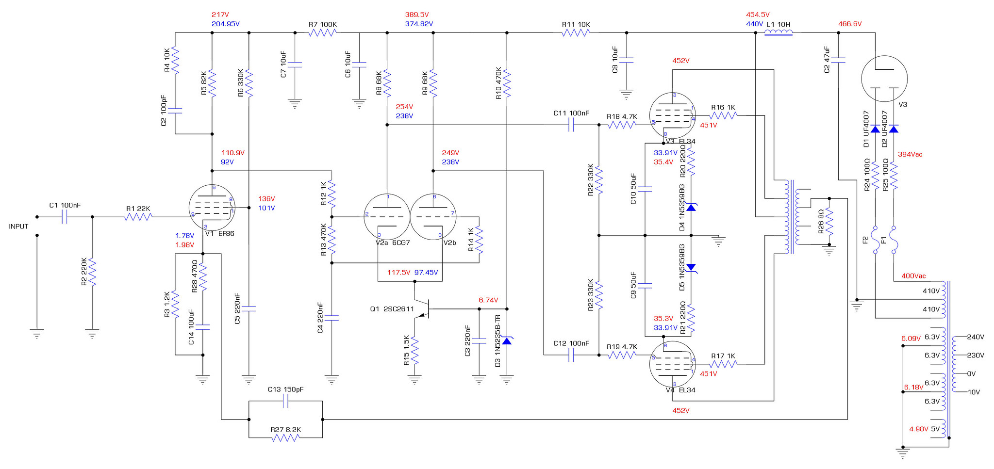
This is the schematic exactly as built. Blue voltages are the simulated values from LT spice. Red are what I have measured.
50123579927_f1898eed9a_h.jpg
 
Having just re-checked my drawing of the CCS board and the datasheet for 2SC2611, it appears that I have successfully mirrored the transistor connections. I've connected the base and emitter backwards which would explain quite a lot. It was wrong in my drawing which is why when I checked it, I missed the error.
 
Took the transistor out and checked it. It tested ok so I put it back in the correct way around and reran the test with no feedback. Voltages seem to be a fair bit better, possibly a bit low if anything, which I can correct by moving the primary over to 240V instead of 250V.
50124872423_e2a518508d_k.jpg


Some slight oddities I noticed:
- The measured voltage at the anodes of 6CG7 differ by 3V
- ~100mV of noise on the anodes of 6CG7 at idle
- EF86 clips on the positive half of the waveform @ ~70mV which throws the balance

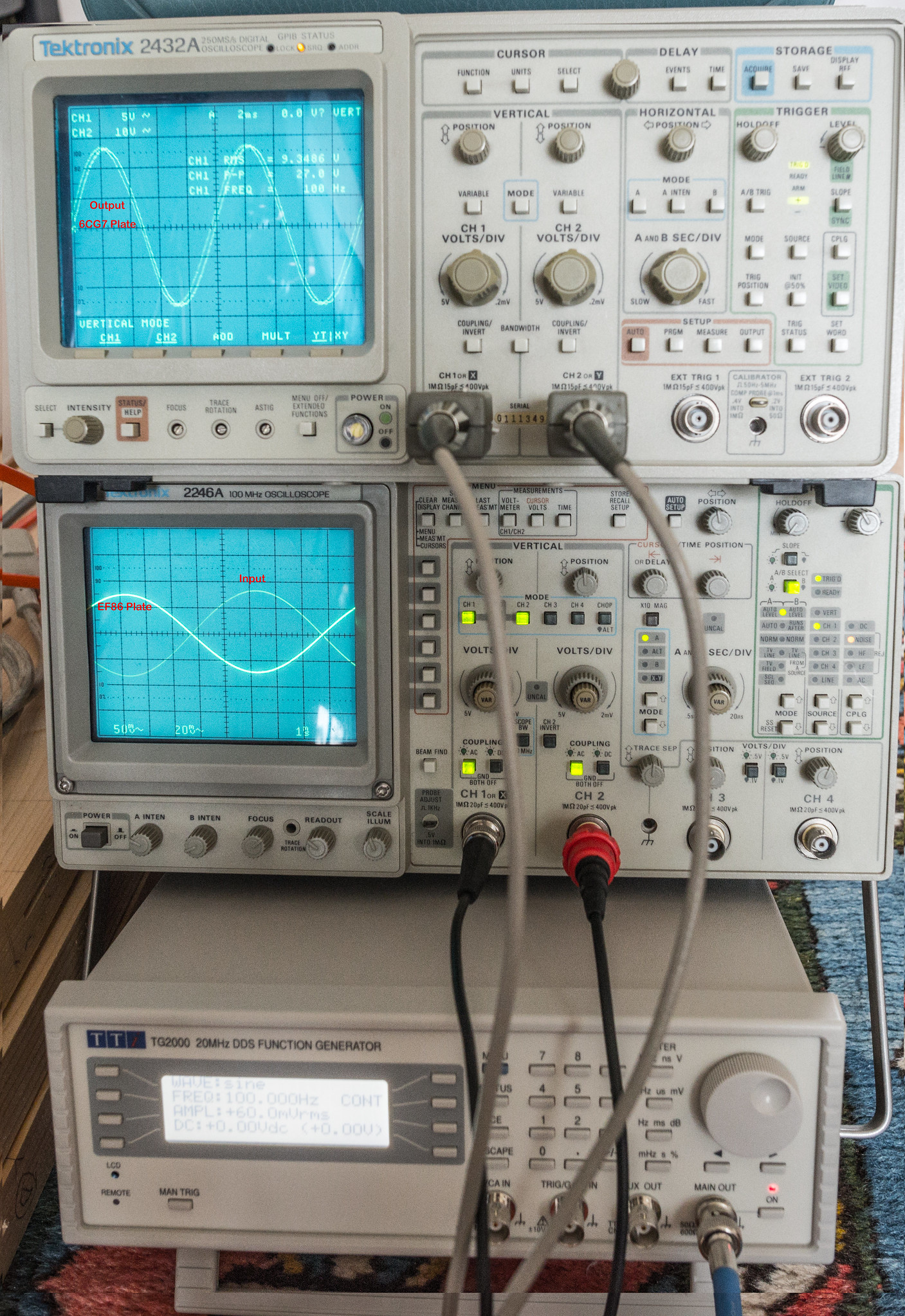
This is an example of what I mean by the limited output power. It's clean at 60mV input across the whole frequency range.
50125445246_4e83b7f65c_k.jpg


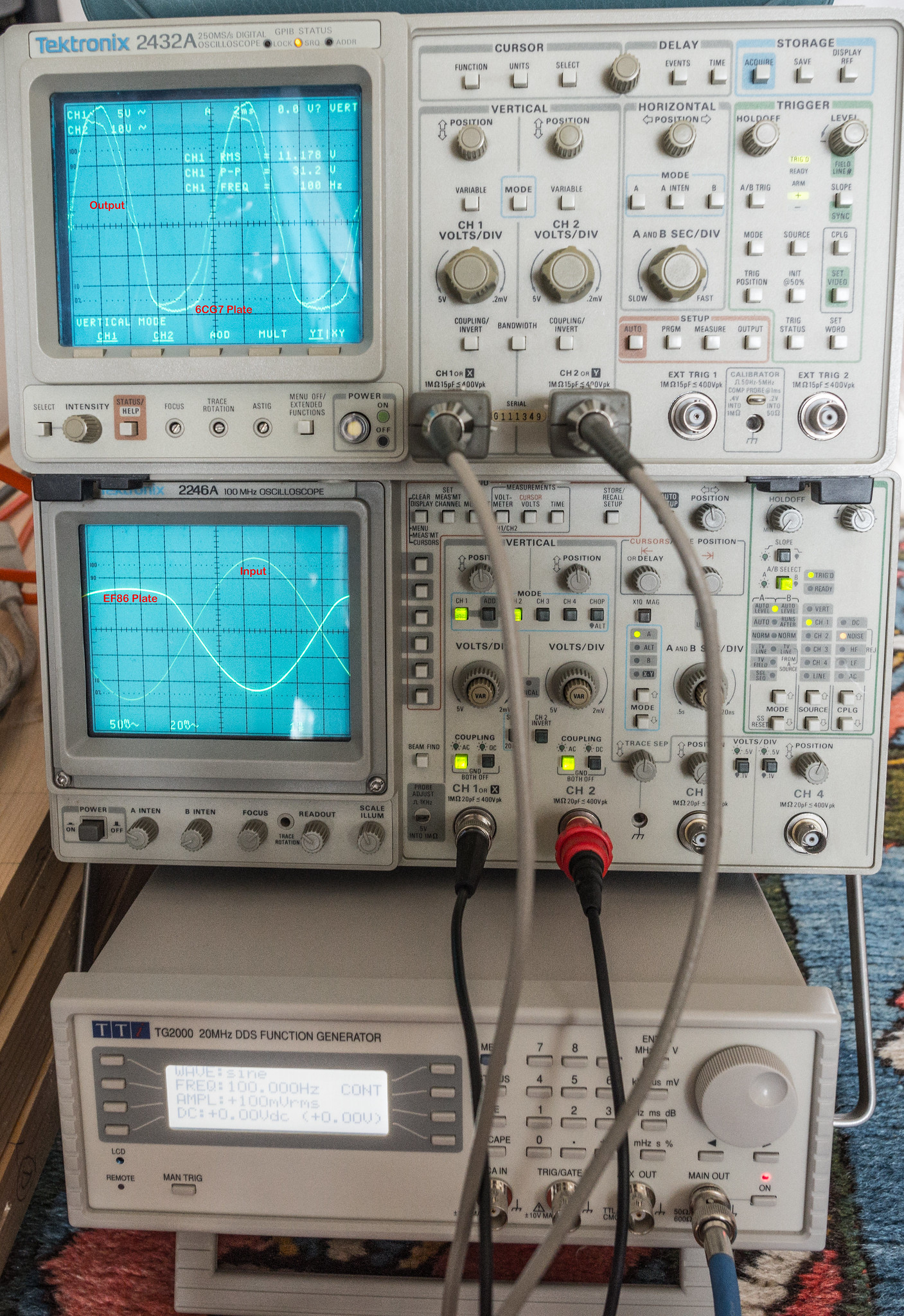
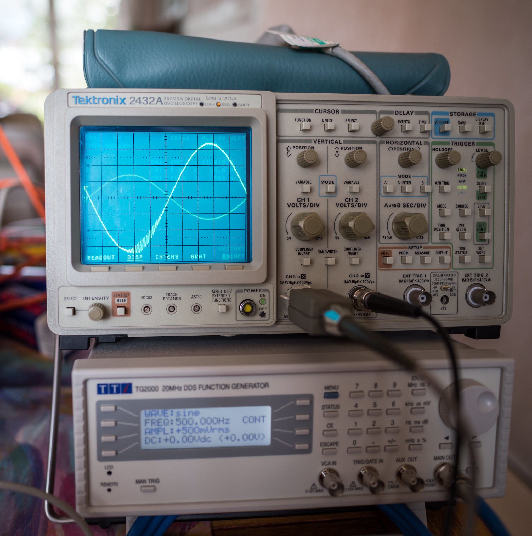
It starts to distort around 80mV and by 100mV input it's well gone.
50125445106_5c546b8a12_k.jpg
 
The scopes are really getting on a bit now but still more than up to the task. It would be very nice to have a modern slimline, quiet scope with a colour screen to make differentiating between channels easier.

Doing some further testing this morning using a 6267 instead of the EF806S and saw much better results. (102V on the plate) What was not so good is I also noticed that half of the HT winding was only showing 10Vac and the other half 390Vac.

Checking the mains transformer winding resistance across both halves shows it as open circuit vs my other one which shows 168ohms. It's spec is 410-0-410 @ 180mA which I would have thought is sufficient for this design. I think it'll have to go back to primary windings.
 
Presumably D1, D2, R24, R25, F2 and F1 all "as expected" ? If only half of tx giving volts would you get a very unsmoothed DC out of V3?
Yep all as expected. Essentially, the amp has been running with half wave rectification. The one half of the HT winding is definitely gone, I'm just not sure why. The HT winding is supposed to be overspecced as the amp as standard is supposed to be ~145mA draw with the option of 40mA for a pre-amplifier/radio receiver. 6CG7 has a greater draw than the original 12AXX&/ECC83 but it should easily be within the comfortable limits of the rating on the transformer.
 
I'm now wearing my "disappointed at myself face" and the dunce hat.

I took the transformer out today in order to pack it to ship back and thought I'll test it again. The "dodgy" side now showed about 1Meg resistance to centre tap which I thought was a little odd as it was totally open circuit yesterday and wiggling the cables showed no difference. Removed the crimp and tested after stripping back some insulation and it all measures good now.

I'm having a rethink on the crimps. I checked the wire and can't see a size printed on what is there as, typically, the wire length is too short to have all the text there and each of the 4 HT leads is missing that bit of text. I'd assumed based on the fact that the other wiring was 18 AWG and 20 AWG that this slightly slimmer stuff was 22 AWG. These red (more like pink) crimps I've got are for 16-22 AWG. I would solder the connections but I feel the plastic body of the fuse holders isn't particularly heat resistant. Do I splice in some thicker cable and crimp that or do I buy 22-26 AWG crimps?
 
All reconnected now with solder and sleeving. Voltages are now much higher after the rectifier. I think I still need to tweak the resistors around EF86 to get the operating point closer but it's not too far out.
50141734492_4b2da19bbd_k.jpg


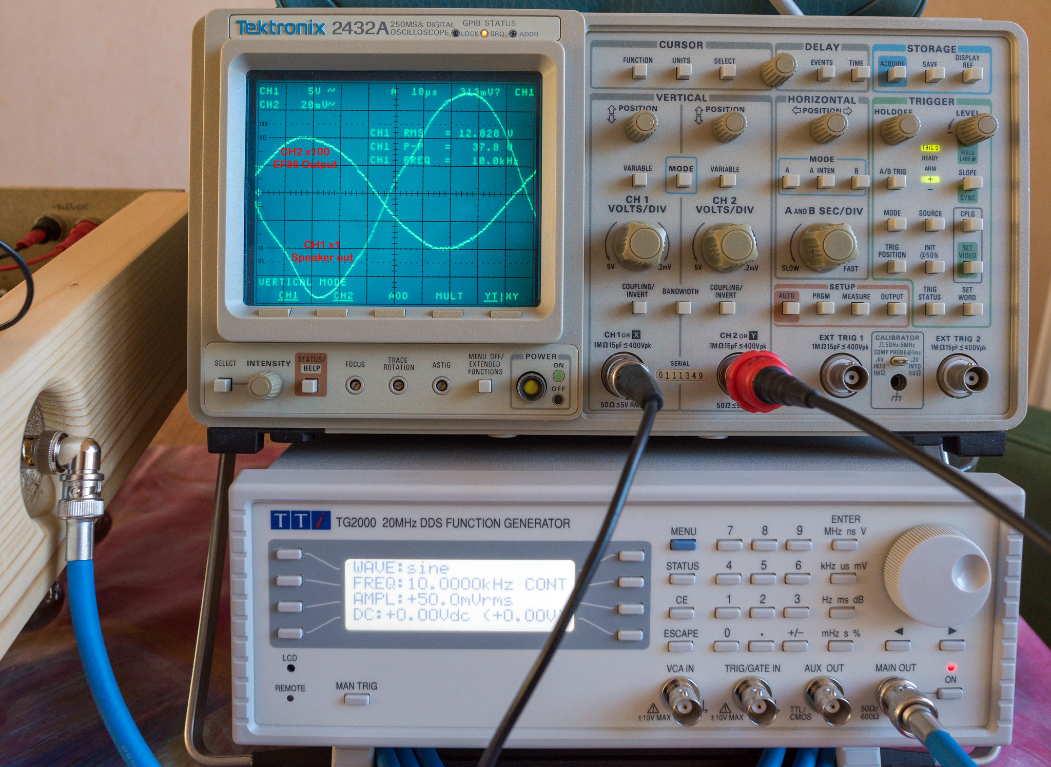
It's performance doesn't look too bad without feedback. Certainly better than the 12AX7 phase splitter. It still gets quite out of shape around 11Vrms output, particularly on the negative cycle. I'm guessing that the V1/V2 operating point is still playing it's part in that. There's also the obvious signs of crossover distortion too.
50140953958_968cc426a8_k.jpg


Even a 10K square wave doesn't look bad. The frequency response is remarkably flat at lower power outputs. Towards that 11Vac output, the response starts to fall slowly from 14KHz.
50140954453_967c26dfba_k.jpg
 
Interesting to read / watch as the story unfolds! Those voltages look SCARY.
I've seen over 500V a few times. The one time I tested it without the output valves in place I saw well past 500V. It's still very small in comparison to the EHT in old television set cathode ray tubes. IMO, my F&T 47uF capacitor which is only rated at 500V is probably going to need to be replaced as I'm seeing a brief peak of 510V at switch on which isn't going to help it's lifespan.

I made some adjustments to the cathode on EF86 and ran some tests. First thing I tried was removing the 100uF cap and 470R resistor leaving only the 1.2K resistor in place. Zero effect observed, voltages remained the same. I then swapped out the 1.2K resistor for a 1K. I also swapped out the JJ GZ34/KT77's for EL34B/5AR4. The JJ GZ34 clearly has more sag than the sovtek 5AR4 as the voltages out of it were ~10V higher. The behaviour of both V1 & V2 seemed to be far better with the voltages being much closer to expected. I also noticed the asymmetric distortion on the output has now gone, only showing slight signs of crossover distortion as the output passes 13Vrms. (21W into 8 ohms)

This is how things were with just the cathode of EF86 changed.


Changed the R6 screen grid resistor to 470K as I wanted to actually see the effect on the voltages across both V1 & V2. I was surprised at how big a difference it actually made everywhere else, yet the screen voltage change was pretty small.

V1 Anode increased by 26V, G2 decreased by 8V and the cathode decreased by 0.15V. V2 anodes remained the same but the cathode increased by 11V.

Anyway, I put the 330K back in as that seemed to produce voltages in line with expectations considering the higher supply voltages. I can't remember where I read it but it said about the screen being a 1:4 ratio with the anode, so 82K*4=328K.

Here is a short video of it under a music test run with speaker attached. (not hifi sound here as the D810 mic isn't great)

I actually left it run for nearly 6 hours as it sounded great. Not a hint of red plating (anode hot spots) this time, all looks healthy in the glow department.
50152158083_c697b749b1_k.jpg

50152157783_0df5554180_k.jpg


In principal, I'm now left with the challenging part of closing the feedback loop and keeping things stable. No mean feat.
 
What does this mean in practice?
The main reason to do it is that it cancels out some of the distortion, it helps to flatten out the frequency response at the extremes and it also lowers the output impedance. I've plotted the open loop frequency response at both 1W and 20W on a graph here. (6CG7 rebuild sheet) The frequency response falls off a cliff below 50Hz and above 10KHz. Feedback will flatten this back out to an extent. The low frequency response is affected to a certain extent by the input filtration I've applied to avoid sub sonics causing havoc.

Anyway, closing the loop didn't entirely go to plan as the usual feedback issues returned. However, things were not necessarily as bad as they had been with the previous builds.

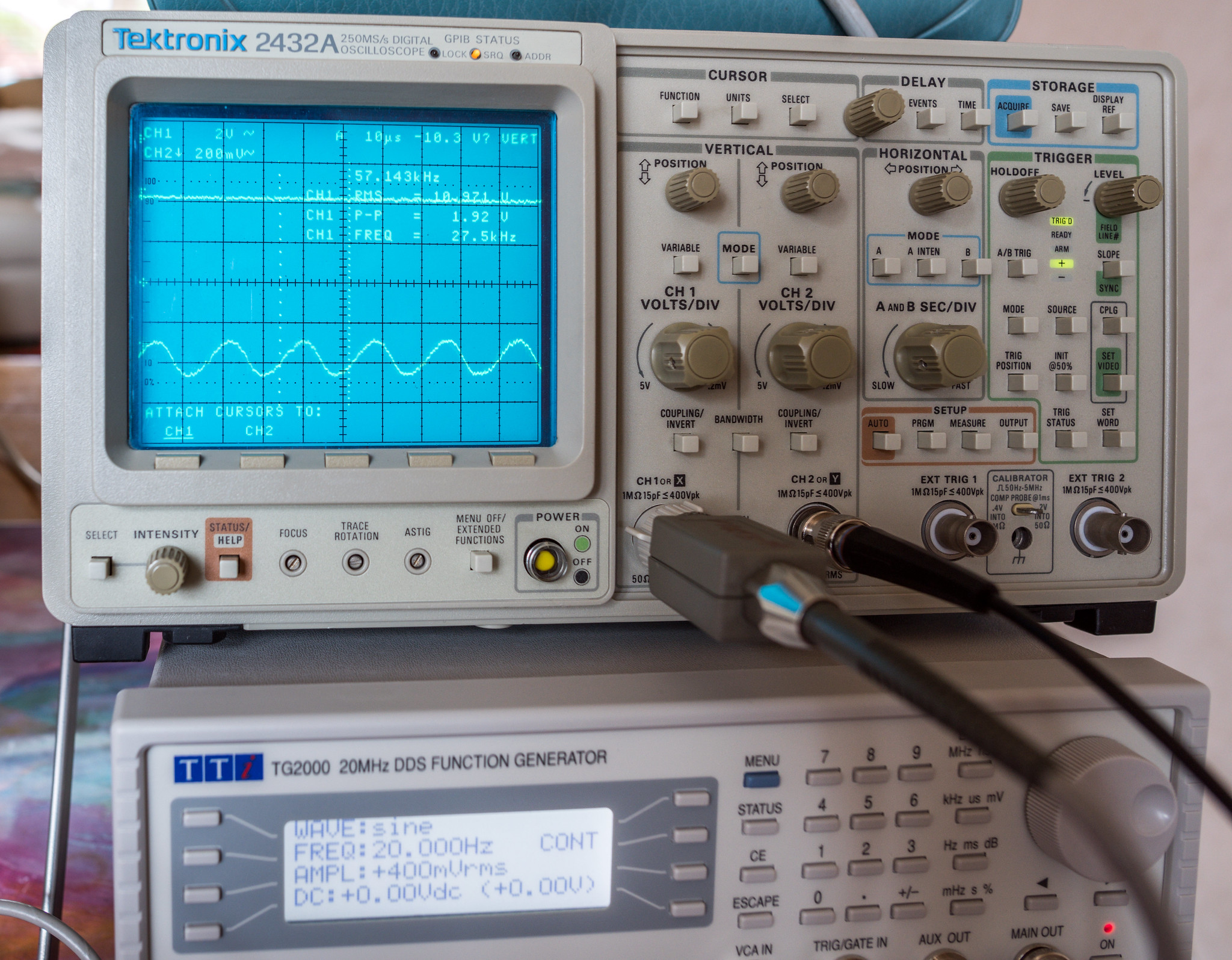
The usual 58ish KHz ringing observed as signal size rises. (shutter speed caught the screen mid refresh hence the dim readout text)
50154371798_8b9c3ad6f2_k.jpg


Zoomed in on the oscillation
50155932467_d3053fb52e_k.jpg


Made some tweaks to some component values which made a decent improvement but didn't fix it.
Comparison at 100Hz 500mV input. Left is C11/C12 @ 100nF & R4 @ 10K, right is C11/C12 @ 470nF & R4 @ 22K. C2 was 270pF for both.
50155932072_6f860a9d8d_k.jpg


On some suggestions from the DIYaudio folk, I made some further modifications by adding a base stopper resistor on the CCS to make sure that it is unlikely to ever oscillate. A 110R resistor added between the base of the transistor and the capacitor & zener.
50158116458_e9fa4982a5_h.jpg


I also looked at reducing the amount of feedback as it had been suggested that I may have a greater level of feedback than originally planned. This meant increasing R27 from 8.2K. After a quick search through the components on hand, I put in 10K and rechecked. A small improvement but not much difference.
50158667701_67bd22f018_h.jpg


It made sense at this point to look at how much gain there was in the system at each level in order to figure out where things lay.

Open loop gain = 49.54dB
Closed loop gain with R27 @ 8.2K = 27.31dB (22.23dB feedback)
Closed loop gain with R27 @ 10K = 28.75dB (20.79dB feedback)

That explains a lot. The design calls for 17dB of feedback so even with 10K in there, I'm still way past that point. Looks like I need to up R27 to ~18K and try again. Fingers crossed that does the trick.
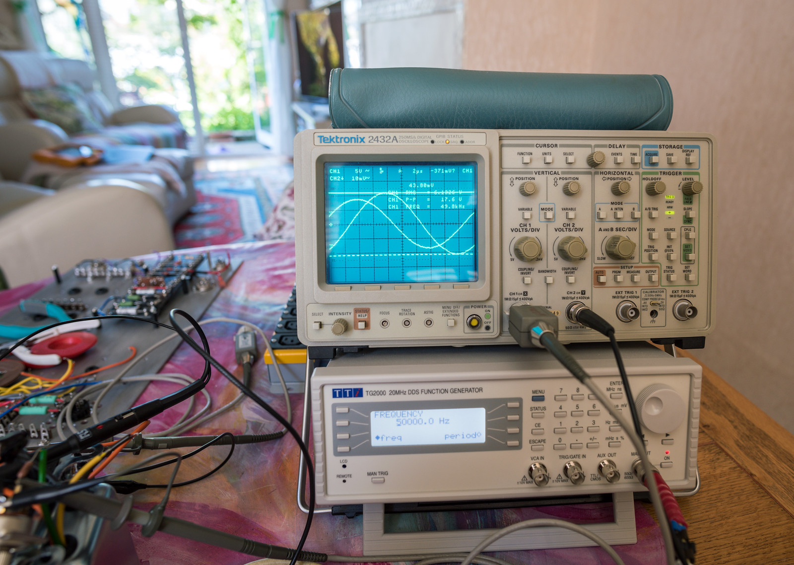
 
I dug out an 18K resistor and did another test run. It now appears to be stable. With R27 @ 18K I'm seeing 33.26dB gain so about 16.3dB of feedback.

This is how things look now.

100Hz @ circa 11.5Vrms out (matches the previous testing)
50160360457_d9d365c1f6_h.jpg


100Hz @ the limit before it distorts heavily
50159565043_432ae35dda_h.jpg


20Hz @ the limit
50160115151_4a61e37273_h.jpg


1KHz square
50160115451_7ee351bd69_h.jpg


10KHz square. The rounding over at the rise and fall appear to be in the input signal if taken after the input veroboard suggesting stray capacitance?
50160115771_a431d5f16d_h.jpg


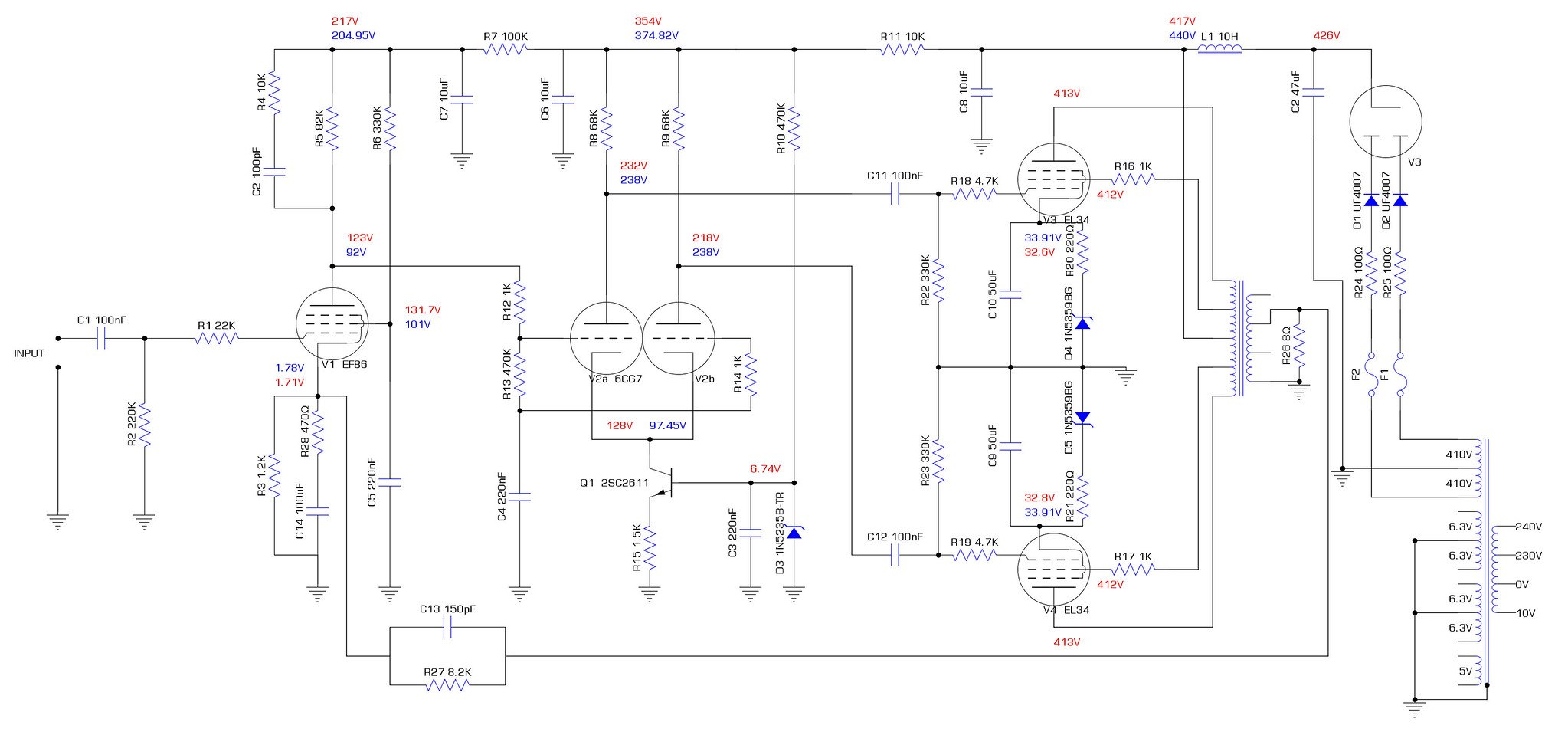
Schematic as things stand. Also note the voltage at C2 and L1 are quite a bit higher than the model. May explain the additional power before clipping starts.
50159577478_5adbe731dc_h.jpg


Overall, I'm extremely pleased as I've had hell getting this thing stable. The output transformers could be a bit better which would likely have net a small improvement in HF response and probably made the feedback loop a bit easier to stabilise.

Major trial by fire, I have run it all day on the other set of valves. It has passed with flying colours and sounds great. Now I need to build the other one. Ideally though, I need to build it all on a smaller chassis as this one is a bit big.
50163013981_df26e1dbe1_h.jpg
 
Last edited:
Some way to go then for a 5.1 system!
Lol, that would be some cost not to mention the heat output. Just the one monobloc generates quite a lot of heat.

As for 5.1, I've got three stereo solid state amps that currently fulfil that role.
16355504660_c74a33c237_h.jpg


Anyway, in other news, I've tested all of the valves I have on hand and have found that the new Tung-Sol EF806SG appears to be duff as it causes excess hiss and simply doesn't sound right, but the older GE 6267's work fantastically. (6267 is just the american numbering for an EF86, EF806S is a lower noise construction EF86) I can't easily distinguish between the jj KT77's and the EL34B's. I guess we'll see which last longest. I may get a set of EH 6CA7's just to complete the array of choice I have for this pentode/beam tetrode family. I will say that in a looks contest, the EL34's win because who doesn't love a good bit of blue glow. No sign of red plating either.
 
Last edited:
How long should valve amps last?
Only experience I have with that sort of thing are nixie tubes. And some of those have had quite a short lifespan. But I suppose these valves wont be on for long hours, just occasional use, unlike the tubes I've used.
The lifespan depends entirely on the construction quality of the valve and how they are used. In the early stages of my design saw the valves showing signs of excessive dissipation with parts of the anode structure starting to glow. (Known as red plating) This exponentially shortens the life if left to run. If limits are respected and the idle bias is set conservatively, they should last a few thousand hours. The little noval valves in the voltage amp/phase splitter stage see such low currents that they should easily last many thousands of hours. (10000 hours is not unknown)

Do you have your own power station to run that lot?
Thankfully I almost never run it all at the same time.
 
Last edited:
Back
Top Bottom