Scratch build valve power amps

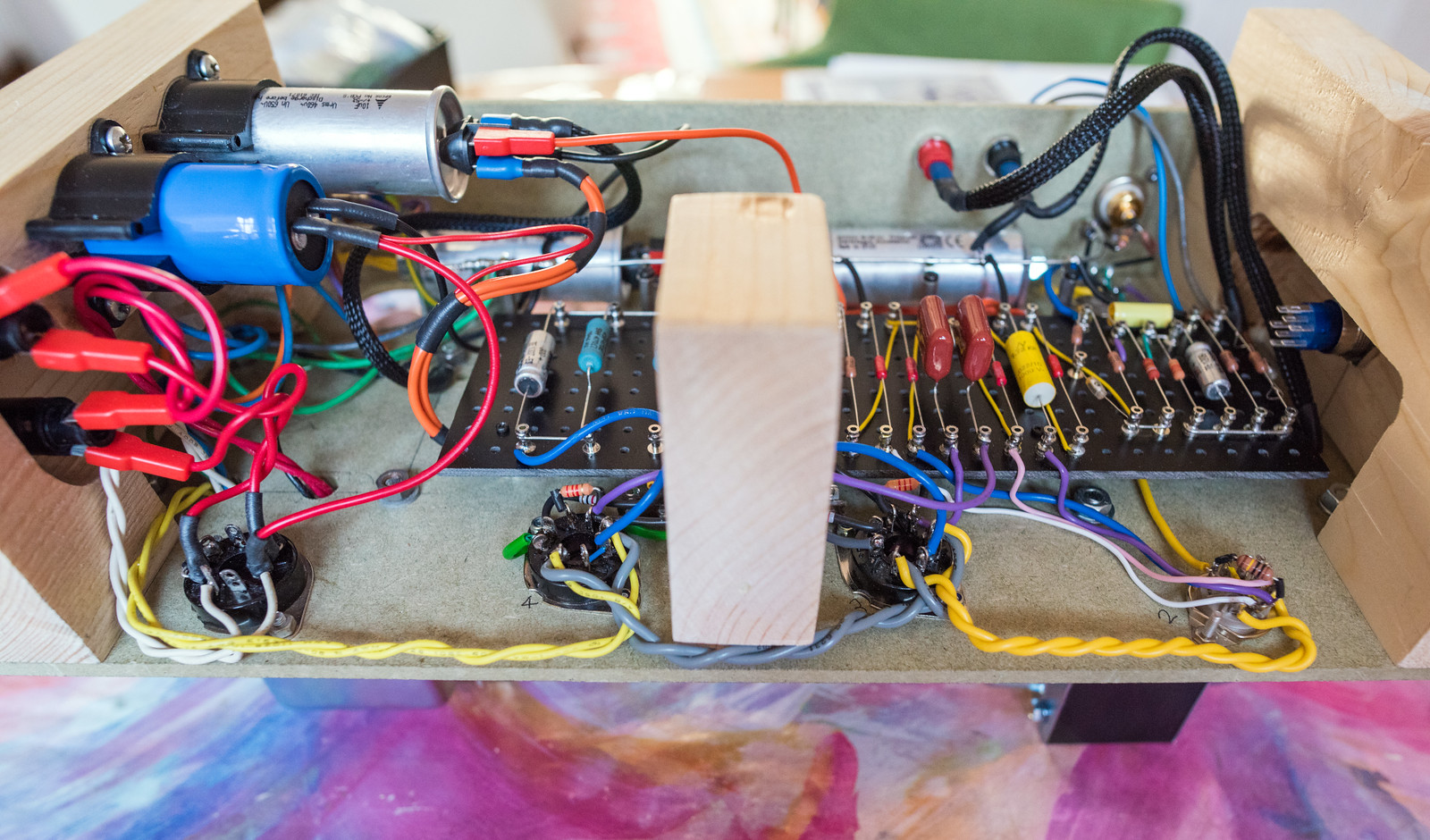
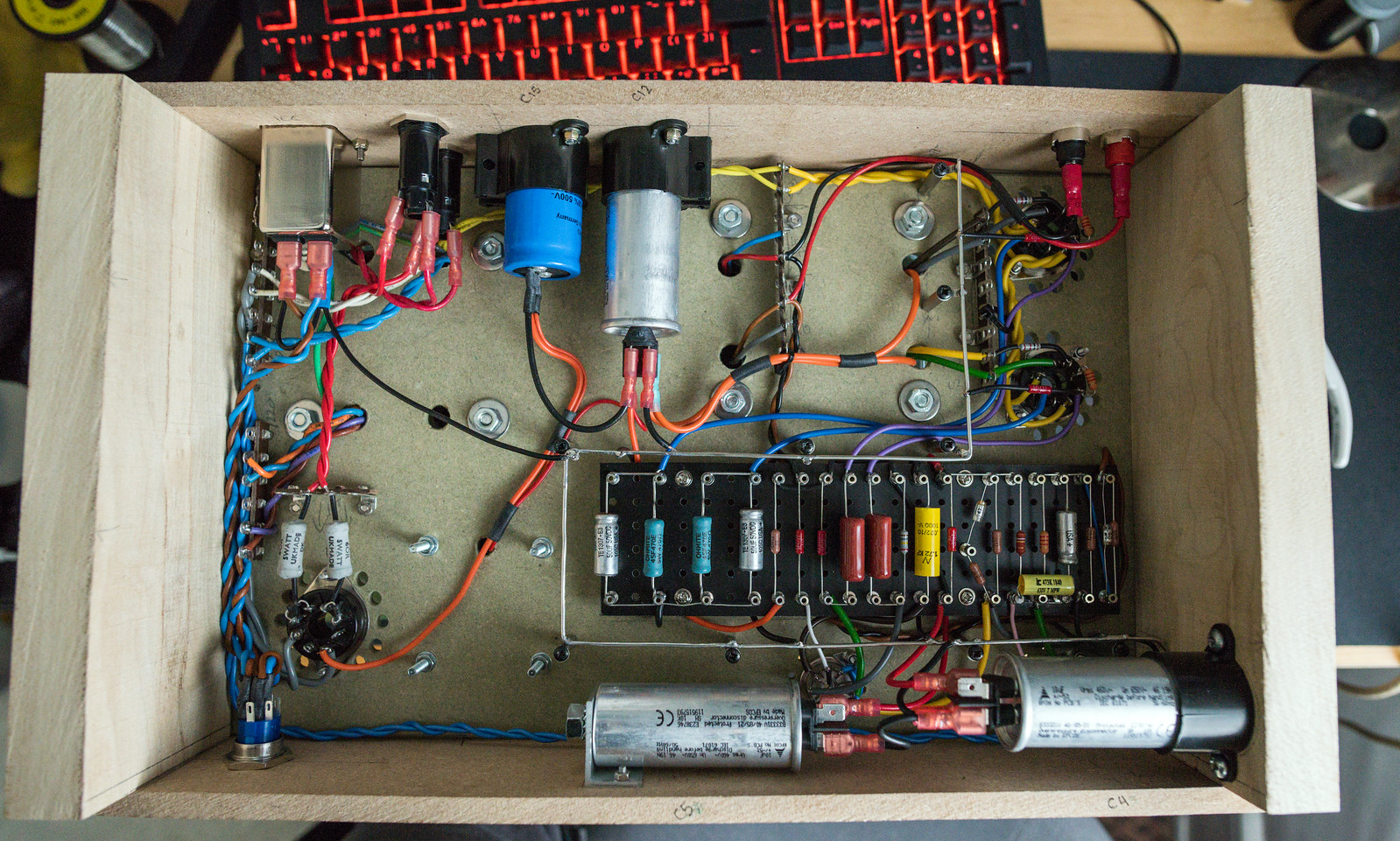
Today's progress wiring things up. Bar the heater wiring, the EL34 sockets and the ECC83 sockets are completely wired up. I've got to make another small notch in the central support so the heater wiring can pass through avoiding close proximity to the rest of the wiring to the sockets. I've also got two slim pieces of MDF that I will use as side panels which ought to help brace things as well as provide a mounting point for the input socket and speaker outputs.

Mid way through the day.


Done for the day.
 
Last edited:
It certainly looks awesome
Thanks. It ought to look significantly more awesome when I get the metal chassis machined.

Today's progress.
Side panels cut and fitted along with the input socket. Speaker output sockets will be fitted when they arrive tomorrow.


Heater wiring probably isn't the best as it's my first go at it and it is definitely quite difficult, especially with stranded wire. All that is left to sort now is the heater wiring to the input valve.
 
Last edited:
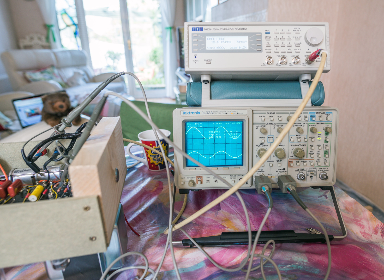
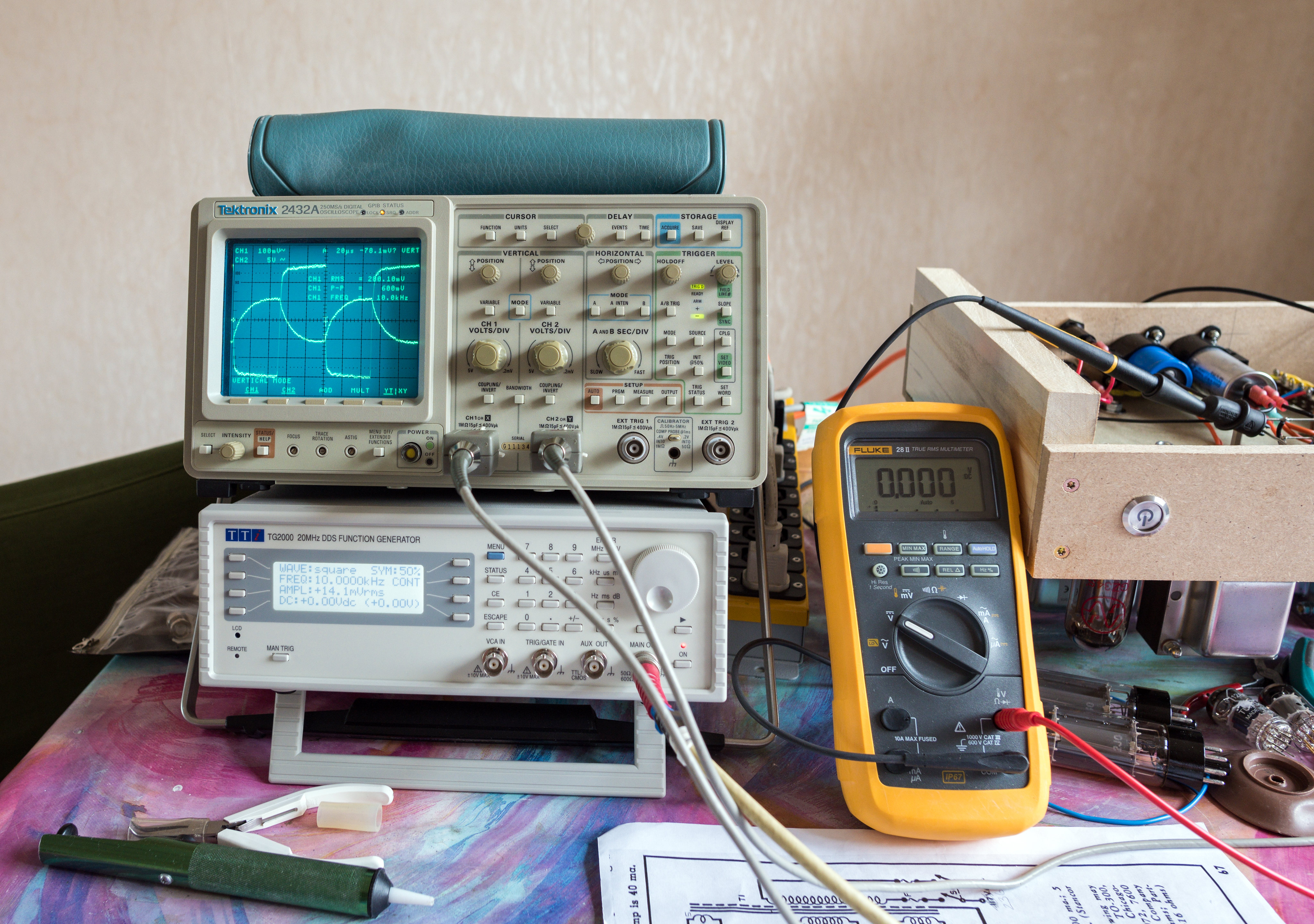
Bought a TTi TG2000 signal generator in the bargain section on CPC for roughly 40% of it's normal going rate. Very handy to have since my Lindos LA101 is playing up for some reason.
 
Last edited:
Lush. Didn't event occur to me I'll be needing my scope but it'll be useful if things don't go well.

You've inspired me to dig out a guitar amp kit I bought 5 years ago. Cleared the kitchen table and I plan to use my 5 day weekend to finish it :)
Knowing my luck, this prototype build will work perfectly and when I reconstruct it in the aluminium chassis, it'll not work properly. Good luck with your build.

All of the wiring is now complete. Decided that I'd used excessively thick cable to the heater on the ECC83 so I dropped down a size for the EF86 as it has fairly low current draw. 4mm banana terminals fitted and only the 8 ohm tap wired up. I'll tie off the 16 and 4 ohm taps.


Last edited:
Went through the whole thing today with my father and spotted only one mistake. Went from pin 6 on V3 to C11 and pin 6 on V4 to C10 which was backwards. I also decided to rewire the heaters on V2 and V3 as the gauge of wire was more than needed.


Re-ran the unloaded test this evening and checked the voltages, all fine with no issues. Then tested with the valves in place. B+ peaks at 496V which is a tad too close to the 500V rating on C15 but it falls back to around 450V pretty quickly. Other voltages seemed fine, the valves glow seemed normal and the transformers remained cool but there was quick a lot of buzzing and my dummy load got very hot fairly quickly which was a tad worrying as there was no input connected. I didn't have enough test gear connected for me to feel comfortable leaving it run any longer at that stage. I've got the feeling that it may be oscillating. I will be testing it again tomorrow but with a lot more test gear connected including a scope across the output.
 
Last edited:
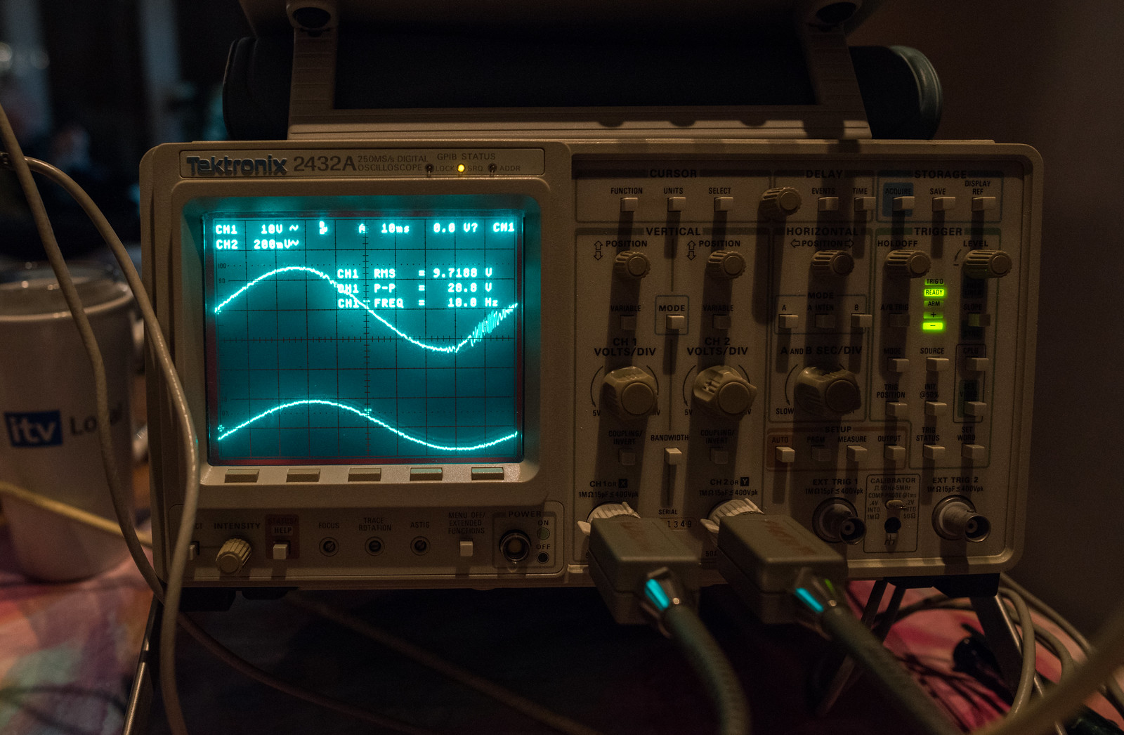
Tested again this morning and got this...

39Hz square wave at 47V p-p.


The good folk at DIYaudio pointed me at the feedback loop being connected backwards. Disconnecting the feedback was on my list of things to try. Just done it and that did the trick. No signal of any consequence out with no input. Testing with the signal generator connected and a simple 1KHz sine input.

Yay... though, holy gain batman 0.05V input, 8V output. (that's 8W into 8 ohms)
 
Last edited:
And it's now sorted with negative feedback connected. I've swapped the anode/UL connections between the two output valves. Tested it with a dummy load for a while getting a load of measurements and checking waveforms.

Voltages - I think some of the higher voltage readings are down to my fluke 28 having a different resistance to the Avometer used for the numbers in the book.


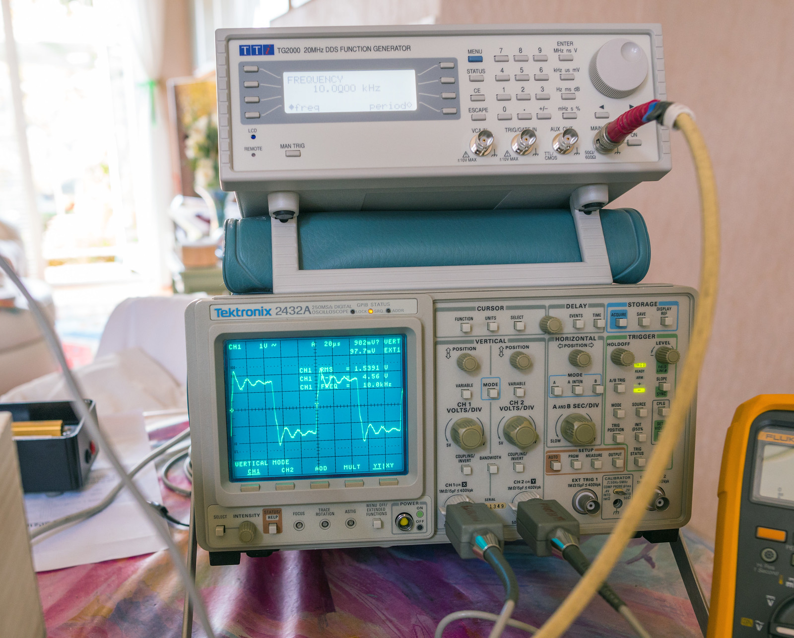
1KHz square wave input shows some ringing. Suggests HF instability.


10KHz square wave input also shows more ringing Sine looked clean out to 50KHz.


Testing with audio and one of my old DIY Kef based speakers. Sounds good and the best news is that it is completely silent, with minimal hiss audible at the tweeter and no hum.
 
Last edited:
That does look like ringing rather than high frequency boost according to this article:

https://sound-au.com/articles/squarewave.htm

Figure 5 talks about ringing - says can be a resonant circuit in the device, but also can be due a transformers' resonant frequency. And if it's outside audible range it's probably not an issue.
It's something that can be adjusted by tweaking the value of C8 in the feedback network. Raising it's value very slightly can reduce the ringing without having a significant effect on the HF response. Going too far can have adverse effects on the HF response and early signs are detectable by ear, usually described as brittle sounding. Ironically, looking at the ringing, it's in the 70-80KHz region which based on further reading on the Mullard 5-20 design seems to be a common oscillation point.

Without any negative feedback, the performance resembled figure 3 in ESP's diagrams.

To be fair, I left it playing music from my phone all afternoon to "run it in" and prove that it was working properly. It sounded fine albeit a bit strange listening to music in mono.

Try some liberal use of 0.1uf and/or 0.01uf ceramic caps see if it goes away.
Based on a lot of reading, I don't think vacuum tubes react in the same way as solid state devices due to things like miller capacitance etc. The liberal use of transformers and chokes seem to have some effects that I'm not used to.
 
The obligatory dark room shots. Dem tubes is looking a bit toasty which is not good for their lifespan. Bias is clearly too hot for them.
49766534936_d0fea242e4_h.jpg

49766864862_04313cd601_h.jpg
 
Last edited:
I've had some problems with rather excessive DC voltages which were causing excessive plate dissipation. (evident in the photos above as the orange glow to the grey metal of the plates in the EL34's) Checking the voltages, I was seeing around 20V more than I should have


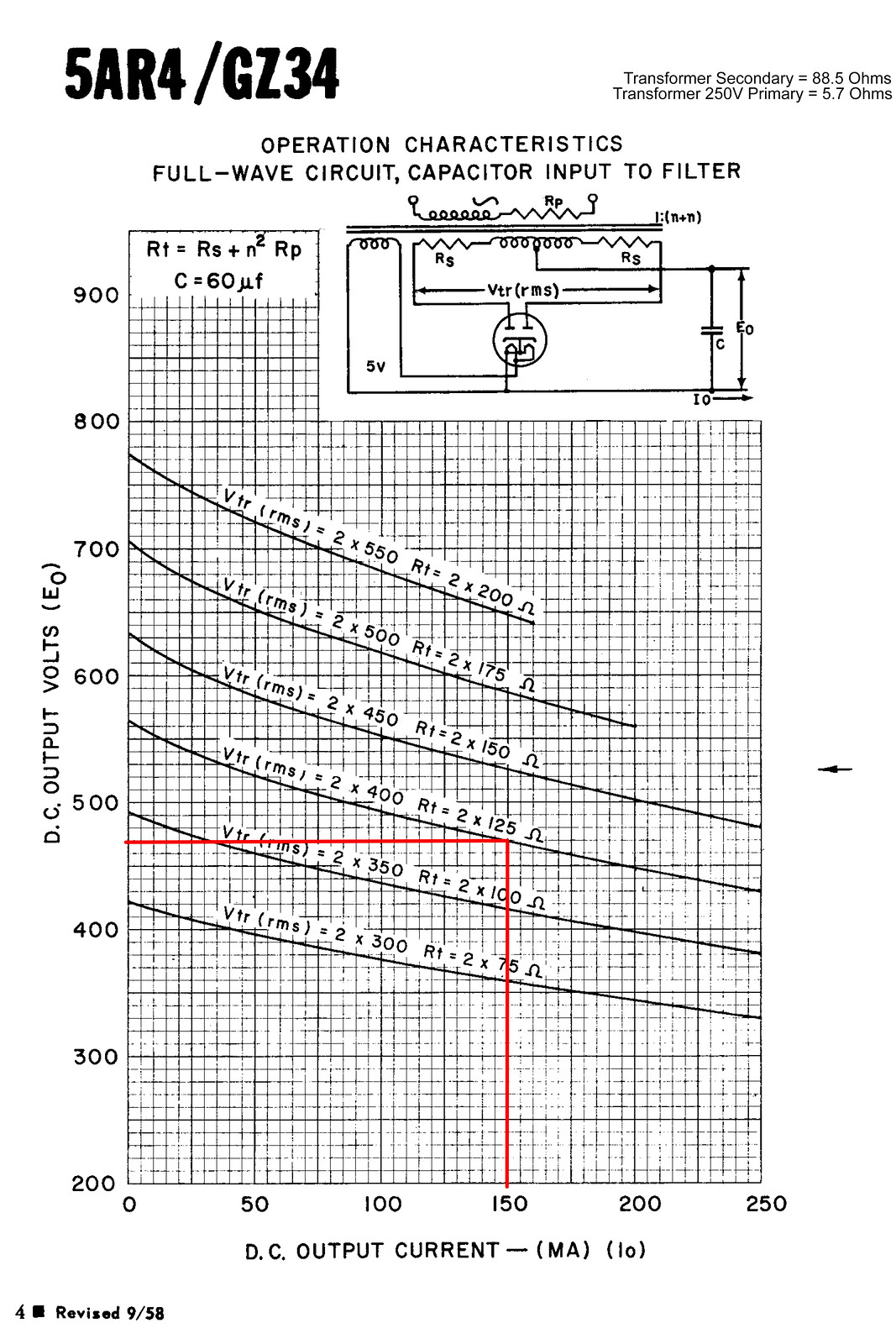
I spent some time going over the datasheet for GZ34/5AR4 and realised that there is a minimum resistance per plate that I'd not realised would need to be checked.

49785213961_2de9d37933_h.jpg


The valve wizard site also happened to have a handy formula for calculating it. (Rlim = Rsec + Rpri × (Vsec/Vpri)^2 + any extra resistance)
V Pri = 250
V Sec = 398
R Pri = 5.7
R Sec = 88.5
Result = 102.9464448

This put me a tad short of the 125 ohm minimum at 2x400V. (although they only list it for 60uF filter) I spent this morning having a good dig through my component stash and found a pair of 5W 60R vintage RS branded resistors which I've fitted in the 410-0-410 feeds from the HT fuses to the rectifier socket.

49785531947_1003ce6d1e_h.jpg


These are the measurements I got with these 60R limiting resistors in place. The numbers look significantly closer to the book figures now. I'm doing some testing this evening and will check with the camera to see if there is any sign of glow in the plates.

Mains voltage - 237.3Vac
HT voltage - 391Vac
C15 - 458Vdc
C12 - 441Vdc
C5 - 410Vdc
C4 - 165.5Vdc

V4 Anode - 431Vdc
V4 G1 - 0.7Vdc
V4 G2 - 433Vdc
V4 G3/Cathode - 30.9Vdc
Heater - 6.0Vac

V3 Anode - 431Vdc
V3 G1 - 0.6Vdc
V3 G2 - 432.5Vdc
V3 G3/Cathode - 30.4Vdc
Heater - 6.0Vac

V2 Anode 1 - 303.6Vdc
V2 Anode 2 - 303.7Vdc
V2 G1 - 88.4Vdc
V2 G2 - 80.4Vdc
V2 Cathode 1&2 - 92.8Vdc

V1 Anode - 88.8Vdc
V1 G1 - 0 (no signal)
V1 G2 - 110Vdc
V1 G3/Cathode - 2.1Vdc
Heater - 6.2Vac

The plates now look much healthier, though the camera can still see some infrared. I cannot see it with my own eyes in a pitch black room, so I think it's ok. Still sounds great and no audible noise that I can hear through the speaker although the mains transformer does hum slightly but it's not mechanically isolated from the whole assembly.
49785493821_4ea98bfa46_h.jpg


49785494741_d7432c4ff5_h.jpg
 
Bought some spare valves to save me wearing out the more expensive and vintage ones. The JJ's are cheaper so I can afford to give them a harder time whilst I'm testing trying to debug issues.

Tung-Sol EF806 SG replaces my vintage General Electric 6267
Tung-Sol 12AX7 replaces my vintage Gneral Electric military 5751
JJ KT77 replaces the Tung Sol EL34B
JJ GZ34S spare in case one of the Sovtek 5AR4 happens to fail
49806903192_ce8ecec4a2_h.jpg


Dare I say it, they may actually run better than the Tung Sol EL34B's I was using as they seem to operate more comfortably with the biasing set by the original design. (No signs of any glowing on the anodes) They don't have the holes in the plates though, so they emit a lot less blue/violet onto the glass envelope.
49806852631_cc6f5c9001_h.jpg


The debugging has not been going as well as I'd hoped. I'm pretty baffled by an errant oscillation issue that I know is caused by the negative feedback but I cannot seem to iron it out and I'm beginning to suspect that the current layout is the root cause. Things get a bit nasty when you overdrive it.
49806903852_750fb3f193_h.jpg


Things were also getting quite chaotic with sub sonic inputs, which although unlikely are still a risk when playing records when the preamp doesn't filter it out. This is what things got like at roughly 12W and 10Hz. It was massively worse at lower frequencies as it would do it at 6Hz with only 3.7W out.
49804513818_2b328c6e54_h.jpg


I've dealt with that issue by sticking a 0.01uF capacitor in series with the input which in tandem with the parallel 1meg ohm resistor filters out the LF below 20Hz. The drawback is that there is a definite drop in the frequency response at 20Hz so I may need to drop this value to around 6.8nF.
Graphs plotted for frequency response vs RMS output voltage for a given RMS input voltage. https://docs.google.com/spreadsheets/d/1_TqbGV73X5MK0Hq3FalolIpyPtJxTQTNwEOtzpezPZI/edit?usp=sharing
 
Mk 2 Version...When all else fails, do it by the book. This is pretty much as close to the book layout as I can get. The capacitors may create some fun with the wiring but I don't think it'll be far off standard. The two capacitors that live between the 9 pin valves will be the hardest as it's supposed to be a multi-element electrolytic which I don't have. I chose to go with a pair of 10uF MKP caps originally so I foresee either some major fiddling or me buying a multi-element cap.


The connections to the output transformer from the output valves in the standard design are significantly shorter and the B+ runs in the opposite direction too. I'm also planning on connecting up the mains switch this time. I may even rectify the one 6.3V heater line in order to get the power LED to work too.
 
Last edited:
Progress on the MK2 has been pretty good so far. I've concentrated on the woodwork side of things using yet more scrap bits. The chassis is basically complete. I've decided to put significantly more tag strips in this time to help distribute the wiring about more tidily and following the mullard layout pretty much to the letter. All the large can capacitors are mounting onto the side panels with the terminals being kept as close as possible to their normal locations. I also shrunk the tag board down significantly. There is so much more space inside now, it's much easier to work on.
 
Last edited:
I don't know how you are doing this but it's amazing!

I like this! Following with interest
Thank you both, it's proving to be quite the challenge to do a decent job on the build front. The results will hopefully befit not only the amount of work involved but also the significant cost.

Progress so far has been fairly good. Heater wiring is proving more challenging with the standard layout. I'll also have the challenge of soldering the live/neutral wires onto the on/off switch, making sure they are sleeved and remain twisted.
 
Last edited:
I finished off the wiring at the very end of April. Wired the mains push button switch in this time which is very nice.
49838552048_fa0a20d439_h.jpg


Testing the amp proved that the problems I had with the first build were not related to the layout. Still cooking valves for no good reason.
49839090421_3d6757c2d3_h.jpg


and still getting unsettled towards the 20W it should be able to output cleanly.


This led to me looking at the Claus Byrith modifications which converts the front end from a pentode input to triode strapped input. The rest of the modifications are far more difficult to achieve as it would require a negative supply. This has the alterations needed to the turret board. Thankfully it's simply removing a few components and swapping others. No need for removing or changing the turrets themselves.
49852006761_8da138b8f7_h.jpg


Schematic for this design.
49851468863_f552503fff_k.jpg


This tested significantly better albeit with some issues still lingering so I ended up disconnecting the feedback completely and running some open loop tests between the anodes of the input valve and the phase splitter as there is definitely something iffy going on. 10KHz square wave input, close to square out of the EF86, utter crap out of the 12AX7.
49858992581_03511d6bab_4k.jpg


Took the EL34's out of circuit and tested again. Very suspicious. It definitely looks like the above issue related to stray capacitance.
49866381591_17f04199d6_k.jpg


Someone suggested that the octal sockets having the stray capacitance was a real possibility since the above was measured at the point the signal would enter the grid of the EL34. I replaced the old finder sockets with some new belton ones. Things improved a bit.
49873981188_cf5a41f4b4_k.jpg


I'm now working on constructing the metal chassis from scratch with some spare scrap aluminium I have floating around. (19" 6U rack blanking plates) I was thinking of using aluminium U channel to make up the sides, but having seen @Sam__ 's scratch build project, that bosch rexroth aluminium extrusion system looks very interesting, if perhaps a bit expensive.
 
Last edited:
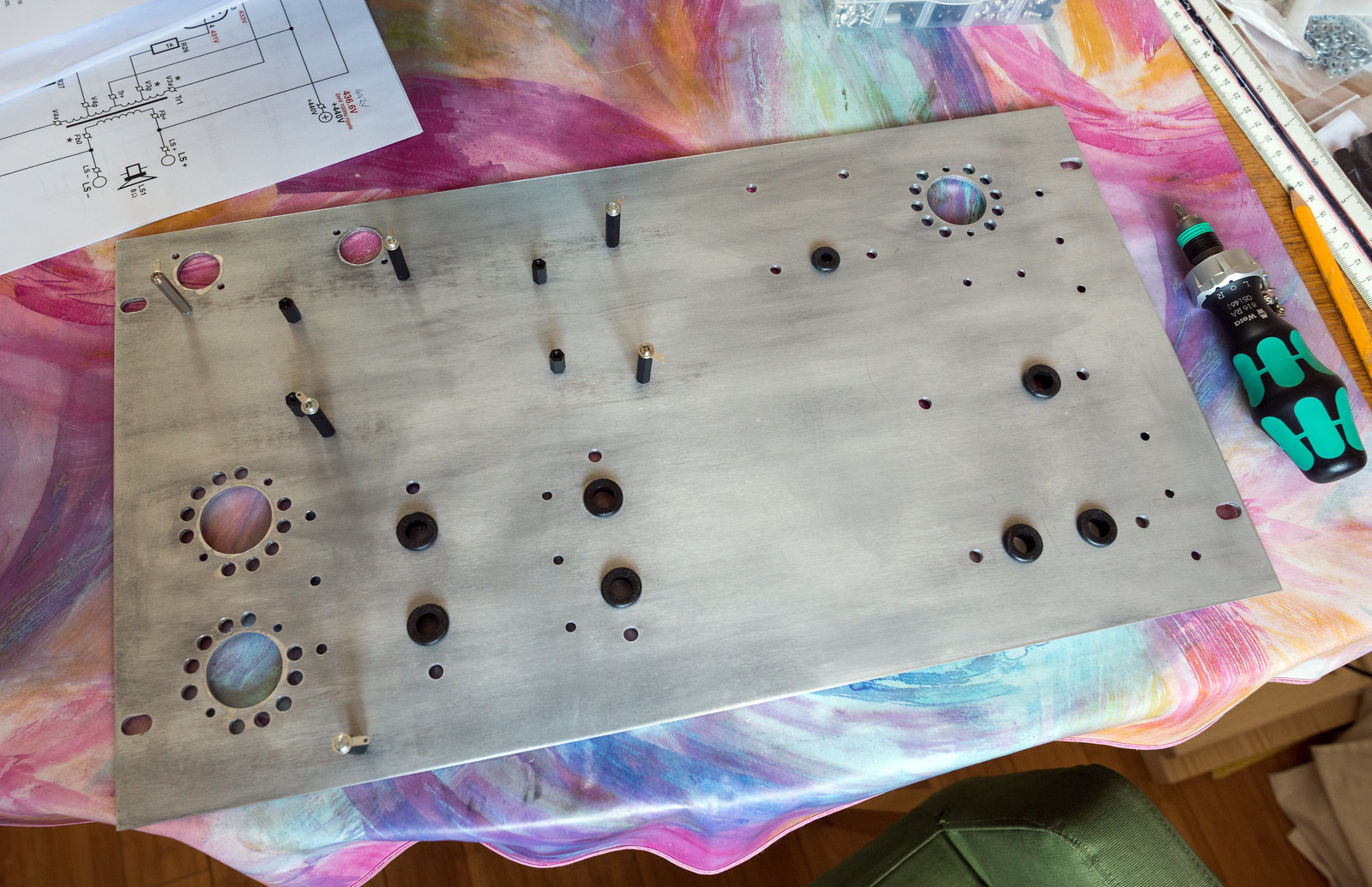
Finally got the sheet metal punches so I've made a start on my aluminium panel. This is re-purposing a 6U rack blanking cover to make the top panel. I've not put the bolt holes for the noval sockets in yet as I had no spare sockets that weren't already mounted to the wooden prototypes. I'll probably leave the cooling holes out for them as the miniature valves seem to run fairly cool. Still got all the holes for the tag strips, earth bus bar and turret board to drill.

49919837993_1721d56f09_h.jpg
 
Finished drilling all of the holes. I've now countersunk those that need to be and fitted the standoffs. Just got to deconstruct the wooden version and transfer the parts across.
49931057336_510ce15d38_h.jpg
 
Impressive stuff, wouldn't have a clue where to start with this. How would the quality you can get with self building compare with bought? ie if you had to buy an equivalent how much would it cost? I know that's not the point, the fun is in the building, just curious.
It can be done quite cheaply if a known build is followed precisely using the same parts as very little in the way of tools is needed. If you have to buy a boatload of tools, it doesn't work out cheaper, particularly if you need any test gear. Oscilloscopes, function generators and audio analysers are seriously expensive.
Solid state (transistors/mosfets) hi-fi can be done far cheaper as there is no need for the extra expensive output transformers and a transistor at worst is about £3. Valves cost anywhere from about £8 up to frankly insane levels. (particularly as they have a finite operational lifespan) The transformers that are needed are equally as bonkers, usually anywhere from £80 out to the thousands.
 
Some changes are afoot. I've decided since the standard design has some known drawbacks with the choice of valve for the phase splitter and I need to make a few tweaks anyway, I may as well integrate some bigger changes. With the help of some kind fellows on DIYaudio I've got the following schematic allowing the change from 12AX7/ECC83 to 6SN7/6CG7 for the phase splitter. A CCS (constant current source) has been integrated into the "tail" in order to force balance the pair and improve linearity. Zeners have been introduced into the cathode bias on the outputs in order to reduce the standing bias but also reduce the losses across the larger resistors that would normally be used to reduce the bias. Whether this bit works or not, at least sonically, is something I'm not 100% sure on.
49946890112_30dabe6da3_h.jpg


New turret board layout. The CCS part is being made on small veroboards that will tie into the turret board.
49946100093_c5db34ba98_h.jpg


The living room table has been turned into organised chaos.
49946880862_919f0be946_h.jpg


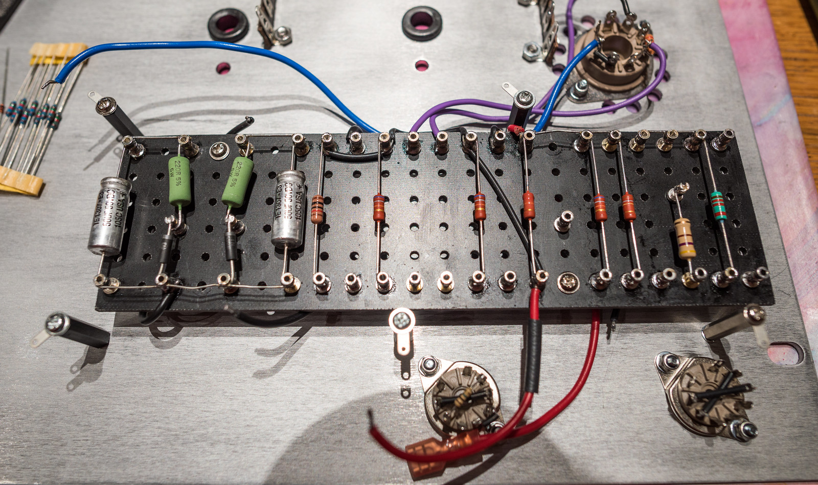
Progress so far. One thing I did discover during my teardown was, what I'd thought was a 220nF capacitor off the link between the phase splitter grids turned out to be a 22nF cap. (which has been that way right from the start as somehow I ordered the wrong value) 3 extra turrets have been added for the new sections.
49946592766_29c967b8c6_h.jpg
 
Last edited:
Back
Top Bottom