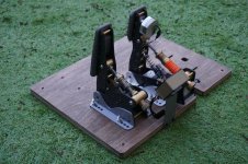
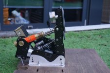
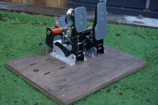
Zee Sim Rig

Thanks again gents!

to address more specifics:

Apologies if you've covered it and I missed it, what do you do for a living?

I really want to add butt kickers at some point, is an amp that size a requirement?

I’m an airbus pilot normally, but I’m off for the winter thanks to the virus...

re the buttkickers no, the amp is arguably overkill but I picked it up much cheaper than the official single channel buttkicker amp, and it’s a 2 channel beasty with really useful USB connection to the PC for some handy settings.

I can massively recommend the buttkicker route, it adds so much immersion in VR that the sim feels broken now if they aren’t turned on.

As always mate, incredible work. You could make a serious killing out of these if you ever decided to manufacturer them. I'm sure the Sim boys would die for something like this even if you charged £££££.

If you didn't want to go to the effort of manufacturing it you could sell blueprints, stls and dxf files.

Are you chaps referring to the pedals? I must admit I’ve considered the idea of making at least one limited run batch and seeing if anyone wants to buy, but obviously there’s a not-insignificant upfront investment in materials and time required and the market isn’t short of pedal options.

I also really need to nail down a clutch design, even though I don’t really use one at the moment (need to build a shifter!).

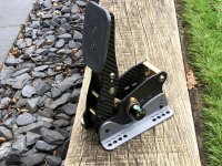
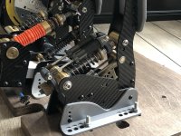
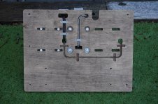
Speaking of the pedals though I’ve just oiled up the plywood pedal plate up and it’s looking much better - just need to decide what to do for a foot rest. I can’t decide if it should be grippy (eg grip tape) or slippy (eg aluminium plate).

I also got the new chunky shock damper for the brake.
eWMpp4s.jpg

21k4AkR.jpg

rTr3Kqe.jpg

tvcjUGs.jpg
 
Last edited:
Gracias!

So here’s a quick little sneak peek of the brake tactile feedback, you can see and hear the resonance motor braaaap as the ABS kicks in or wheels lock under braking.

 
Been enjoying my pedals a bit too much so been slacking on making the clutch....

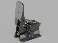
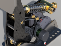
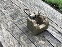
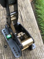
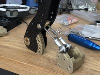
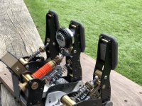
This is the design I've come up with. Basically the idea is it has a little module with a cam profile that bearings will ride along, as you first press the pedal it's going up a ramp and expanding the expansion spring making the pedal require extra force to press. As you break over the crest of the cam profile it stops trying to expand tyhe spring and becomes easier to press... This should give a feel of a bite point to the clutch, and it'll be adjustable where that occurs by sliding the module back and forth in the slot.

On top of that I can make different modules to experiment with feel until I arrive at a cam profile I'm happy with.

What do you guys think, good approach?

iMINGeU.png

DGaTVPn.png
 
Thanks for all the kind comments guys, you'll make my head grow too big!

Real interesting approach to the bite point / over cam feel. I guess the only problems I could see are dirt and wear. Dirt could make the pedal feel gritty, perhaps create a sealed cover for it? Wear you can fix with the materials you use.

Might be a little tight to cover in terms of clearance with the mainspring, but certainly something worth considering for future iterations.... I tend to find that you have to go to one extreme or the other though from experience in CNC - either you want something to be really well sealed, or open and easy to access for cleaning. Something in between just gets dirty and is difficult to clean lol.

Been making some progress on turning the clutch from polygons to something more tangible.

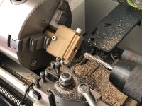
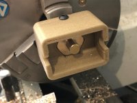
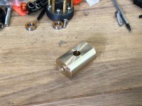
Thought this might be interesting - wanted a much faster and easaier way to make this rear roller part so whipped up some 3d printed jigs for the lathe to avoid the need for slow and painful alignment on the 4 jaw... After making the initial part I then just plop the piece into Jig 1 and do a quick face and drill/ream:

jnF4xiM.jpg

Then pop in Jig2 which has a locater pin and a flat base, then run a quick face on the back side:

tItuue9.jpg

9mheMe2.jpg

Rest of the pedal is taking shape too, only a few bits left to go (still using some temporary parts like the 3d printed side brackets)

Cam Module:

lOS8uOL.jpg

VZzIL0c.jpg


Pedal:

i0FQoRD.jpg
 
Thanks chaps!

@DD_Crash yup, I like toys... I find that as you get older the toys just get bigger and/or more expensive! You in Broughton then? I have seen some pictures of 380 wings being moved, pretty impressive stuff.

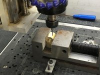
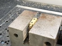
Managed to get a few more bits made for the clutch, this time doing the additional operations on the CNC instead:

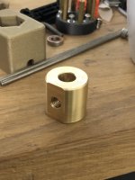
M8 Coupling:

j5BXVNz.jpg

JVzOZfd.jpg


Clutch cam roller, slight redesign here to use rod ends:

R0leyQr.jpg

G804Oee.jpg


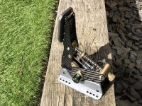
More or less finished, just a couple of 3d printed parts to replace on the mainspring section and a new pinion to print for the potentiometer. Happy to say it seems very promising withthe cam design - I need to get it installed in the pedal plate to test how it really feels under foot but the overall design works great so I'm confident that if needed any changes can be quickly achieved by tweaking the cam profile.

FAvsNgn.jpg


Bonus video:

 
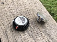
Decided the ABS needed a bit more chutzpah, I've burnt out 2 trying to get sufficient feedback, so after some searching I came across this 40w puck from Dayton Audio... the one it replaces is 25w

I had to make a small mounting adaptor for it as the way it mounts is different, and it's not quite as pretty but hopefully the feedback will be better - will give it a try this eve!

xV0w8E5.jpg

ND7Wcut.jpg


Nice, and thanks!

Just managed to have a few laps of Oulten park, the Dayton audio puck is a big upgrade for the ABS effect - more pulsing, less buzzing and significantly stronger. Happy days!

Just need to have a play with some stronger springs and a few different cam profiles for the clutch until I’m completely happy and we’ll be able to draw a line under the pedals and call them done for now.

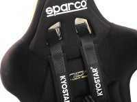
Next up I think I’ll probably be looking into adding a harness and belt tensioner system for braking force simulation.
 
Last edited:
So after stepping up to a beefier spring and tweaking the cam profile the clutch is feeling pretty good with a tangible bite point, but I feel it needs a hydraulic damping element to it for perfection. I've ordered an adjustable slap damper which I'll integrate into the design when it arrives.

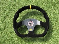
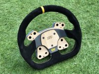
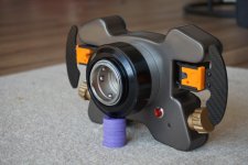
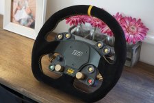
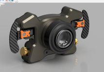
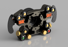
I decided to zig rather than zag and before going to the belt tensioner I thought I'd get around to making a new wheel. I want to add a direct drive wheel base with quick connect, but before I do I need a wheel rim I can use with it. I've designed this new shifter/button box around an OMP knock-off wheel I got a while ago from aliexpress... for electronics it'll be using a BlueHID which gives a wireless interface for the shifters/buttons so no need for any dangling wires like some of the direct drive wheels have.

aKvFtmh.jpg

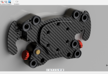
Plan currently is for a hat switch for menu navigation, 7 buttons (for lights, rain lights, wipers, pit limiter etc), rotary encoders for TCS, ABS, BIAS and Map... and of course two magnetic shifters.

Here's the current state of the design, still largely WIP:

EG0ccOm.png


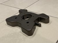
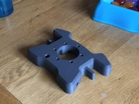
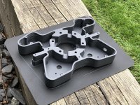
The base is a big 3D print, about 17 hours. I set it off yesterday afternoon and it looked like this:

lREN2xy.jpg


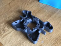
And this morning it's looking like this, still trucking:

5bvsghB.jpg

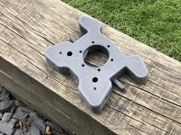
Plan will be to fill/sand and paint the rear same as the FCU style button box so it all matches. I'm using a new material for this which is a modified "tough" PLA - it is tougher than ABS but still very low warp and easy to print... looks like there may be some more tweaking to do still as you can see there are some spider web like wisps but those will easily clean off during post processing.

edit - and done... very impressed with the strength of this material, especially in layer bonding... no matter how hard I try to twist it I can't hear any delamination cracking and it's extremely rigid.

UXq9LHD.jpg

c2oAMmX.jpg
 
Last edited:
Hah, reasonable is subjective!

It's always been a problem with this sort of stuff - if you are going to mass produce something it's pretty easy to get things down to a good price and a good margin. Making small batches or one offs is comparatively very time consuming, and of course time is one of the most valuable commodities of all!

For example it's why this base rig itself just isn't viable really as anything other than an endeavour of love, if I assigned even a measly £15 an hour for my time which is ridiculously low it would price itself out of the market. People in general aren't willing to pay for the time required, a problem my friend that makes bespoke furniture encounters regularly - many can't seem to understand why a bespoke wardrobe made by an artisan (him, I'm not referring to myself as an artisan lol) costs more than the one they can get down Ikea with a side of meatballs.

Anyhoo, Mostly finished the design now including quick connect and charging port on the rear - I welcome any feedback before it progresses to full realisation!

gtT0Lbk.png

Gx7MAu4.png

puqUEDt.png
 
Last edited:
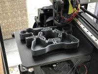
So I wanted to do a few tweaks to the design which annoyingly meant another 17hr+ print!

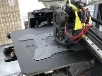
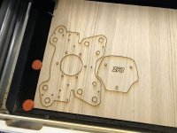
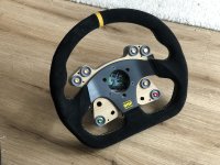
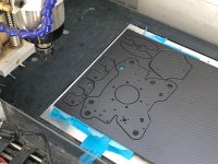
I laser cut some faceplates for prototyping, actually quite like the wood look lol

b0sRW0E.jpg

38IjOAp.jpg


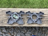
New on left, old on right. You can see where the BlueHID control board sits.

nxLQVdV.jpg

Prototype faceplates (want to make sure positions are all good before committing to CF plate)

1zTFhRK.jpg

gcW1lfz.jpg


Also made some good progress on the magnetic shifters, but just waiting for a couple of parts so will show those in a couple of days
 
Last edited:
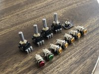
Got delivery of some bits today!

Some nice switches and encoders:

pgMvtCs.jpg

Printed some button guards and fitted to test the ergonomics... pretty happy so will probably make the proper faceplate soon.

K5sLu51.jpg


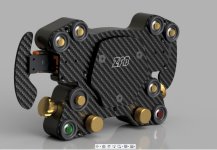
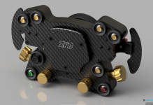
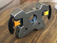
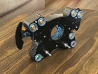
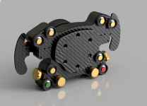
Also did a render of the final version so I have a visual target!

xXjy6Df.jpg


The parts I was waiting for for the shifters arrived too. Very happy with it for a v1 and probably not too much to change.... The big screw at the back is the adjustable end stop but will be replaced with a grub screw when they arrive so won't be visible. Satisfying to use!

kjLa7xX.jpg


Bonus video:


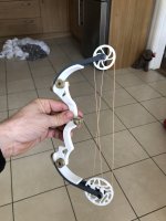
Also as a fun diversion (because I don't have enough to be getting on with lol), I made my boy a mini compound bow on the 3d printer... it's actually a little beast and I think i'm going to win irresponsible father of the year award.
6mtHWWj.jpg
 
Last edited:
Thanks :)

So first things first, after handling the prototype I made a few changes to the knobs, making them slightly larger and easier to use. Here's the render with the new parts

Y9zyDSV.png


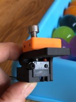
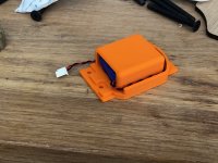
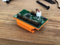
Managed to get a bit of work done today. Firstl I made a battery holder mount for the BlueHID board:

N5bhsPo.jpg

wgZnvaY.jpg


Filling and smoothing the 3d prints is a bit time consuming but does make for a much nicer end product

PuPun8P.jpg

tAGFmII.jpg

osBwup9.jpg


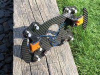
Cut the CF plates:

D398PTE.jpg


I also remade the shifter side frames in CF:

dQdzEr9.jpg


So here's where it is at for now, still needs some clean up (and need some black screws!) :

W8EYIIl.jpg

qFqXzV5.jpg
 
Thanks!

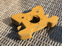
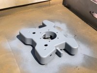
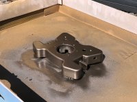
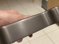
Just wanted to show off the finish after a rub down and wax, I think this probably ranks among my best rattle can paint jobs to date so I’m chuffed with that.

A lot of work though with sanding, filler, sanding, filler primer, sanding, primer, top coat, laquer!

CeKML7B.jpg

ajwFwR0.jpg

In other news, I just recently took delivery of a thanos motion controller... seat belt tensioner will follow and later when I have some cash to burn the thanos will expand to give me full motion support. Exciting times!
 
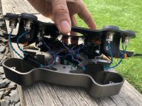
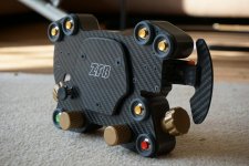
Wheel is basically done, all wired up and working too.

There are a couple of things that still need work - not entirely happy with the button surrounds so will remake those and also need to sort the hat switch surround, but good enough for now!

DyaY9h0.jpg

mFCD8dq.jpg

KZiWGxO.jpg

CfTXePM.jpg

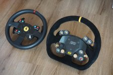
Old wheel vs new wheel:

fQwPx1g.jpg

Next up will be working on the new belt tensioner system!
 
Thanks chaps

Yeah very happy with how it came out, now I just need a direct drive base to mate it with lol. I do have an adaptor I printed out to fit it to the thrust master base, but keen for an upgrade at some point.

The magnetic shifters are a revelation compared to the mushy spring shifters on the Thrustmaster, one of those things where you don’t really realise what you are missing until you try something better.
 
Thanks, very kind as ever!

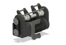
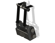
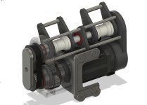
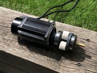
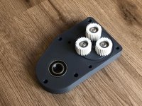
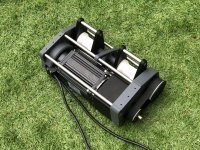
With my Thanos and first 80ST servo motor arriving recently I have been scratching the old noodle about how to build a compact belt tensioner system using such a chunky motor.... this is what I've come up with. Let me know what you guys think! It incorporates a 7:1 planetary gearbox I designed, which should give a slightly scary amount of strangling power when pulling the harness. To prevent untimely demise from an autoerotic asphyxiation incident, I’ve built in some mechanical end stops in the form of those steel rods which prevents the system from being able to tighten past the ~50mm of total travel if anything goes doolally.

PpdpuZ1.png

0Ah5BpS.png

7rT4HR4.png
 
Last edited:
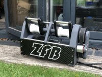
So finished the design for the belt tensioner with a few tweaks, I've also made a few little modifications with a view to being able to add acceleration surge in later using the same unit with either a mechanical or hydraulic pad in the back of the seat to apply pressure to the back when accelerating.

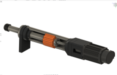
Here is a semi-translucent view so you can see the inner workings of the integrated planetary gearbox:

jqdU29q.jpg

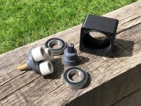
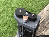
And here are the parts so far:

JEVdxOe.jpg

Yj4BxAX.jpg

ai5uB3C.jpg

8pxy5b2.jpg


I've also made a few other parts but waiting fort some things to arrive in the post before I can assemble.


In other news I've also designed a piggyback damper system for the clutch pedal to give a more hydraulic feel to the motion, helps stop it springing back too fast

AlLJc5X.jpg
 
Cheers!

So who is good at physics?

Rated torque of the motor is 2.39Nm, I have a 10:1 gear reduction now which should I believe give 23.9Nm... The arms of the belt tensioner are at 70mm from centre of rotation, so I believe that gives 23.9/0.07 = 340N of force at that point, or the equivalent of 34kg

Assuming my rusty Physics memory is still correct If we look at peak torque that's 7.1Nm which translates to 71/0.07 = 1014N of force or 101.4Kg pulling on the belt. So in theory at least given my body mass this belt tensioner should be capable of simulating around 1.2g of deceleration at peak torque with sustained levels a more sane 0.4g or so.

Now the really important question - how much force do we reckon it takes to snap a collar bone? :eek:


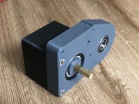
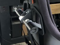
Here are some pics of progress. I'm awaiting the motor mount itself before I can bolt it to the seat (hence the gap you can see between the motor and the gear unit). I also need to make an idler pulley to tighten up the belt a touch and make the carbon fibre cross plate but other than that it's all done.

6KP2cbF.jpg

3xZ561i.jpg

GBE0HMP.jpg


In other news, I decided to sell a small portion of my crypto stash from a few years back, so have freed up some toy funds to pay for a VRS directforce pro wheelbase (when they come back into stock :rolleyes:) and enough left over to cover the costs of building 4x actuators for full motion.... exciting times!
 
  • Like
Reactions: BM3
Thanks. Yeah I think the wheel has been the most pleasing so far from a level of finish standpoint... really happy with how it came out.

The wife disappeared off with the sprogs today for a bit so got a chance to finish off the belt tensioner. Still waiting for the motor mount to arrive to be able to fit it to the chair, but other than that it's basically done. Seriously chonky unit, weighs over 5kg!

LT9Ijuj.jpg

9iwKCv2.jpg
 
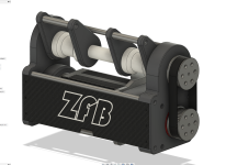
So I've knocked out a design for the motion actuators.... still needs a little refining but the idea is there.

I was originally just going to go with the well known SFX-100 style, but I don't massively like the square look and while they clearly work great I think they were designed very much with the idea that all you need to be able to make them is a 3d printer and no other special tools. Clearly I'm not lacking in tools so have gone with my own design.

Some advantages to this approach - I'm using 80ST motors which are a bit cheaper (about 30-40 bucks per unit which adds up) than the 90ST, give the same power and torque, but have lower inertia so should be more responsive. I've also upped travel from 100mm in the SFX-100 to 170mm which should be useful for flight sims. Finally I can use 3" stainless exhaust pipe as the actuator body which cost me 30 quid vs the £200-300 the profiles would have cost.

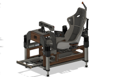
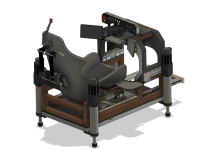
So here's the design (WIP!!):

H1A1778.png


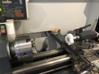
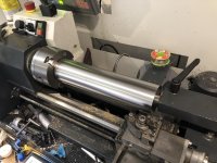
And I took delivery of the steel for the actuator body today... needless to say the exhaust place didn't manage precision cuts so I had to come up with a way to finish the ends nice and square and get the lengths accurate. Actually a bit of a challenge when you are looking at a large steel pipe!

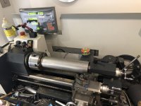
I came up with this 3d printed addition to my live centre on the lathe, which allowed me to hold the pipe solidly in place while machining on the lathe. This allowed the use of my lathe's linear scales too so we can get the tubes to within tenths of a mm of where we want them too.

iKeCuea.jpg


Raw tube, I think it's safe to say we are pushing the size limits of my little lathe lol:

863PimZ.jpg


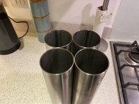
Both ends squared away and quick polish with some scotch pads

4RR9xJH.jpg


All 4 done - nicely matched lengths which will make construction of the other parts easier.

YQfUQ1D.jpg


Roughing out placement on the rig:

6AhNzNY.png

OWvNdZg.png


And if anyone isn't familiar with the SFX-100 style rigs, here is one in action which gives an idea of what the target is.

 
Last edited:
Back
Top Bottom