

- Joined
- 13 Mar 2006
- Posts
- 6,713
Time for an update. ")
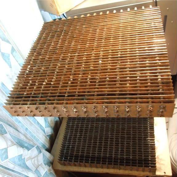
I changed the method by which I put the fins on;- before I had deooxidised the copper pipe prior to putting new fins on, now I instead changed to using strips of 120 grit wet'n'dry with sellotape on the back to strengthen, which I used to sand about 4cm of the pipes, flux and slide fins on (I had already filed the holes of):
PIC OF SANDED PIPES
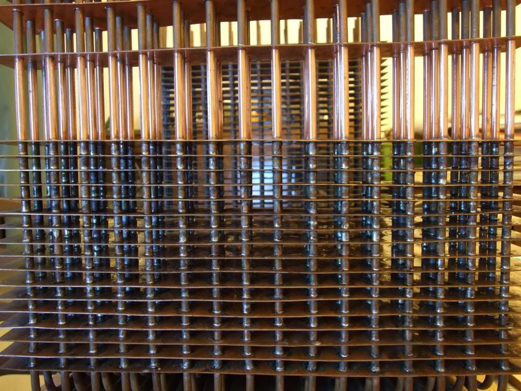
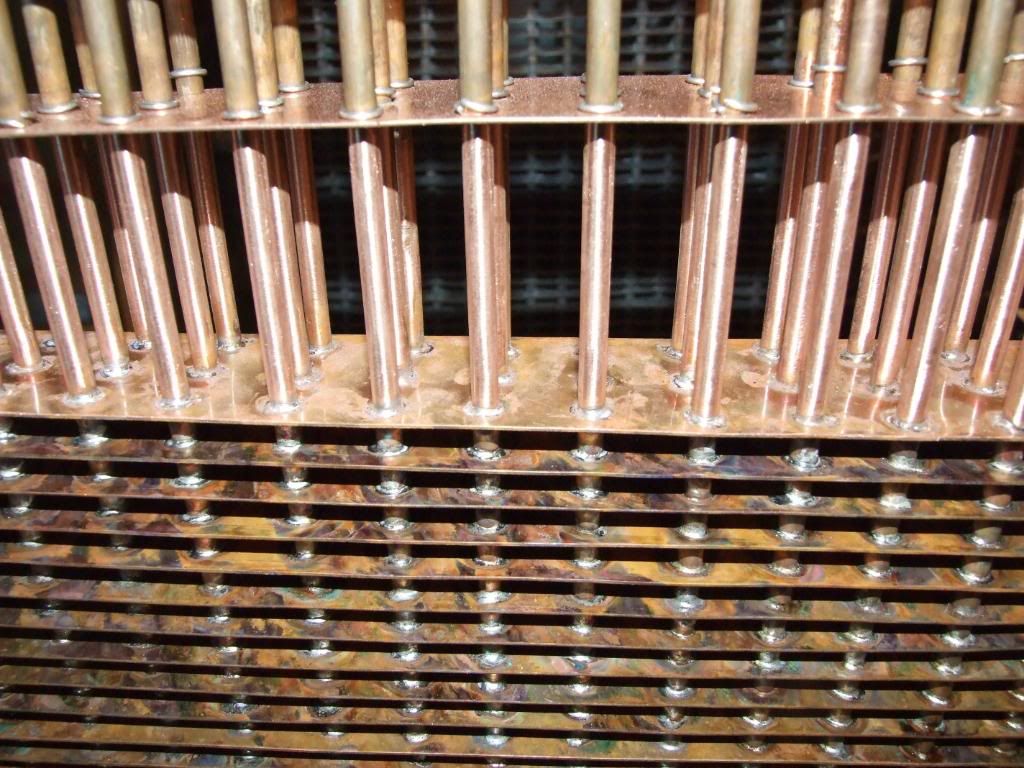
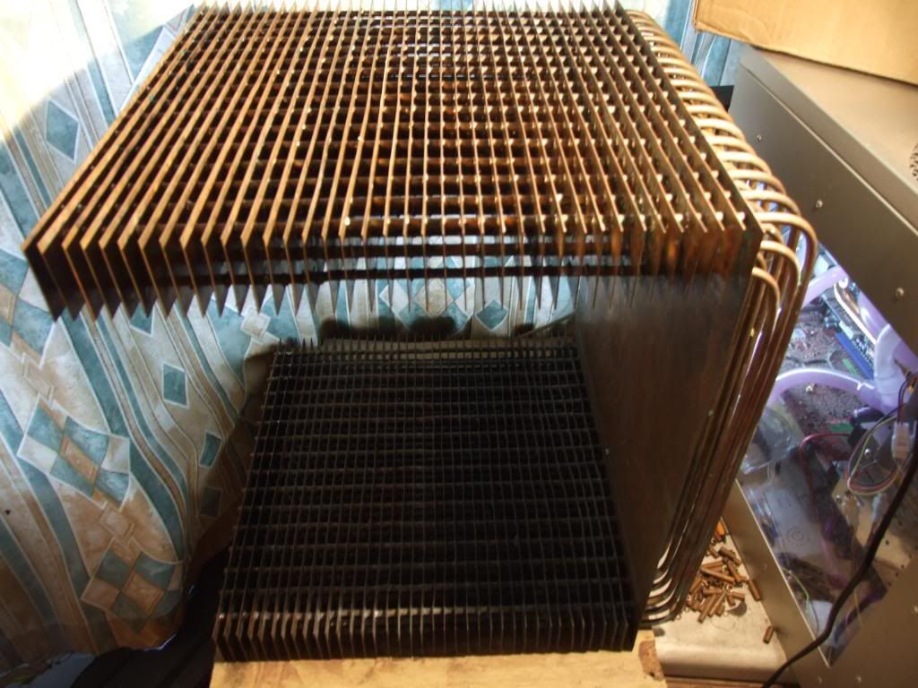
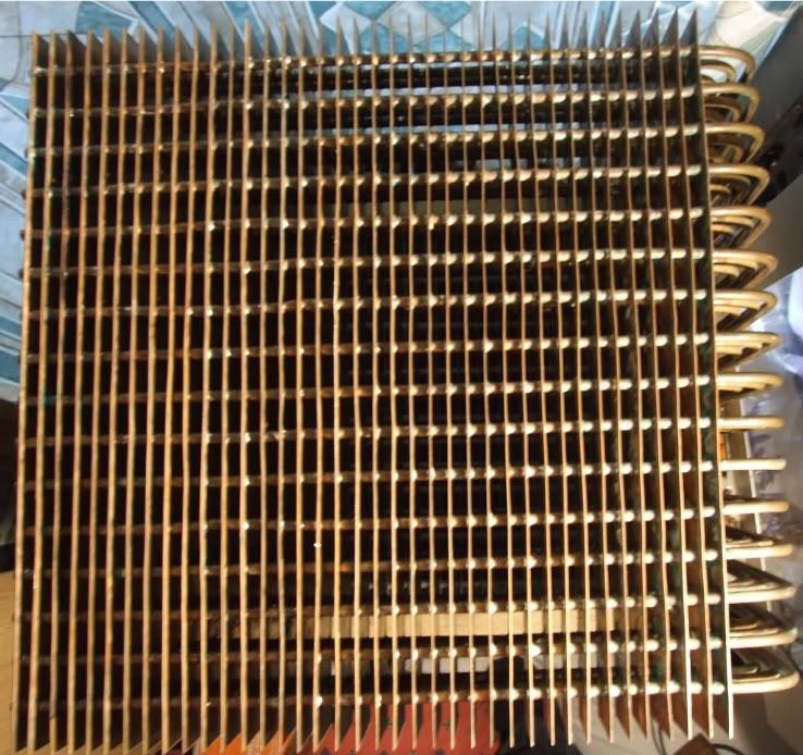
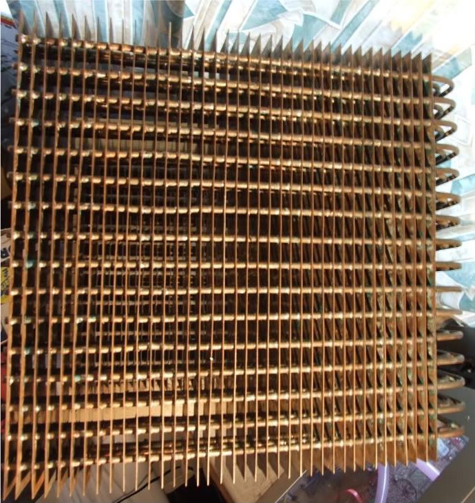
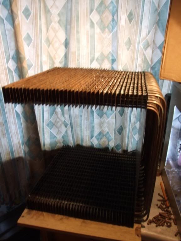
All the heatfins are now on, and the pipes have been trimmed down.
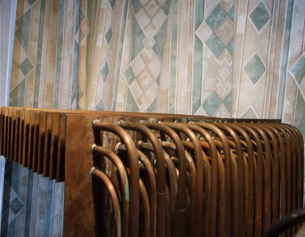
PICS OF MONSTROSITY
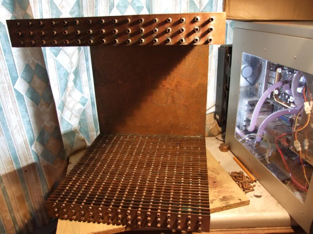
I've decided to make the manifold/plenum from copper - it'll have an inner box made from thin copper (0.152mm thick) joined to the end fin by solder paste, and strengthened with some of the thicker 0.9mm thick copper made from 4 leftover copper strips I had.
My friend Robin has some nice tools and machines, so I asked him to maked the inlet, outlet, fillpoint and drain port for the radiator from the 25mm diameter copper bosses I had.
PIC OF LATHE
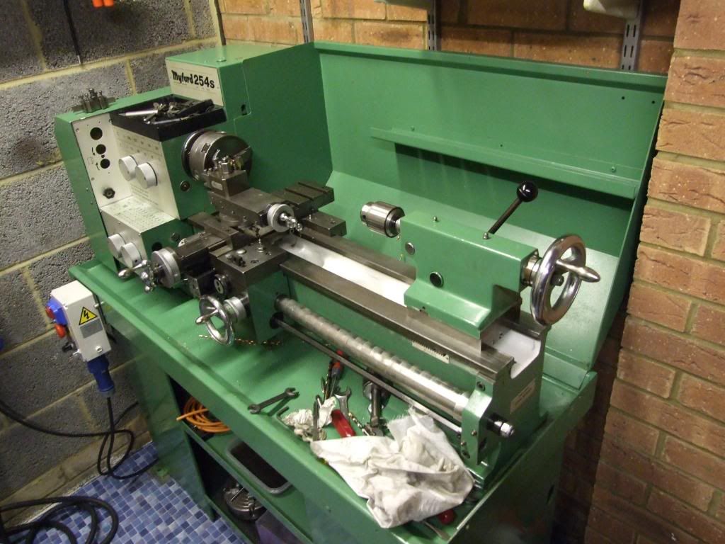
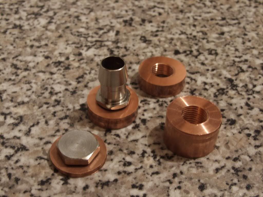
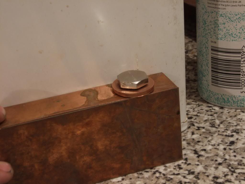
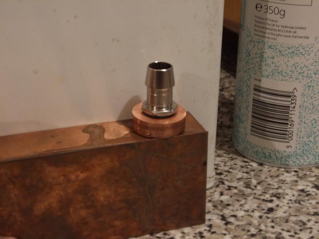
After making 11.8mm holes with the lathe the copper bosses were tapped on the lathe with a BSP 1/4 tap, cut with a circular saw mill bit and then fly-cut on the mill to give a beautiful smooth shiny surface, which doesn't really come across in the photos:
MACHINING
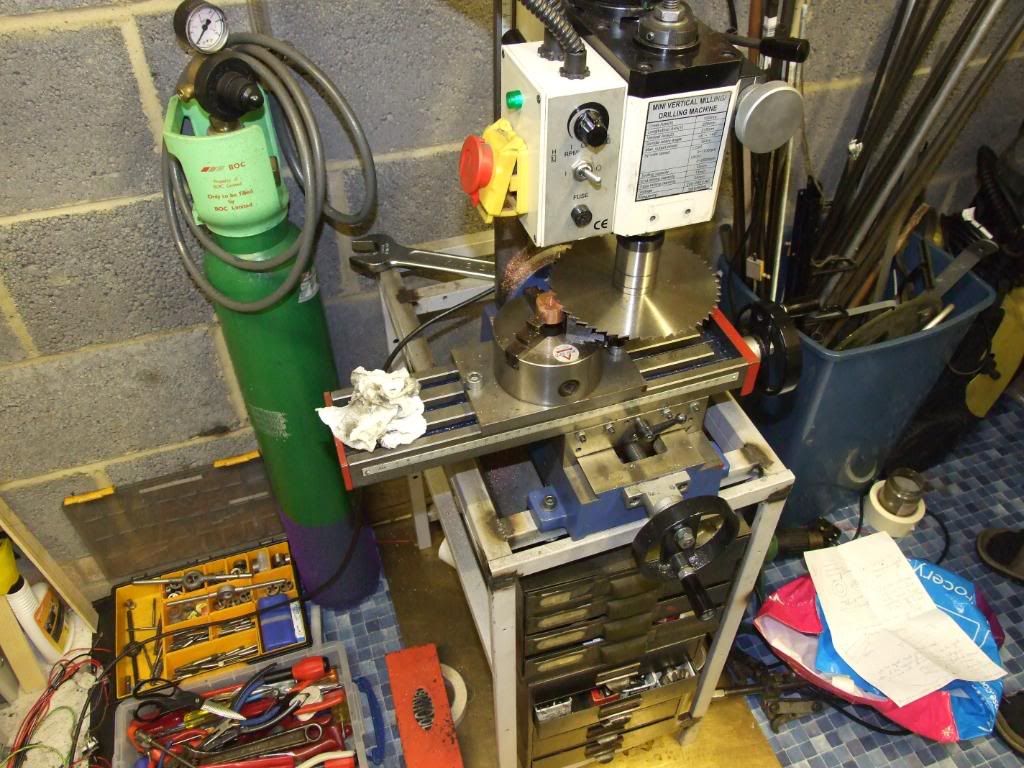
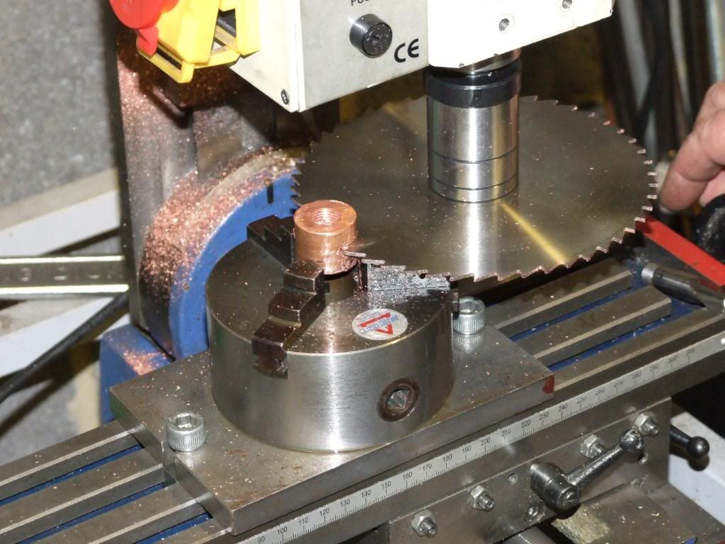
PORTS DONE -
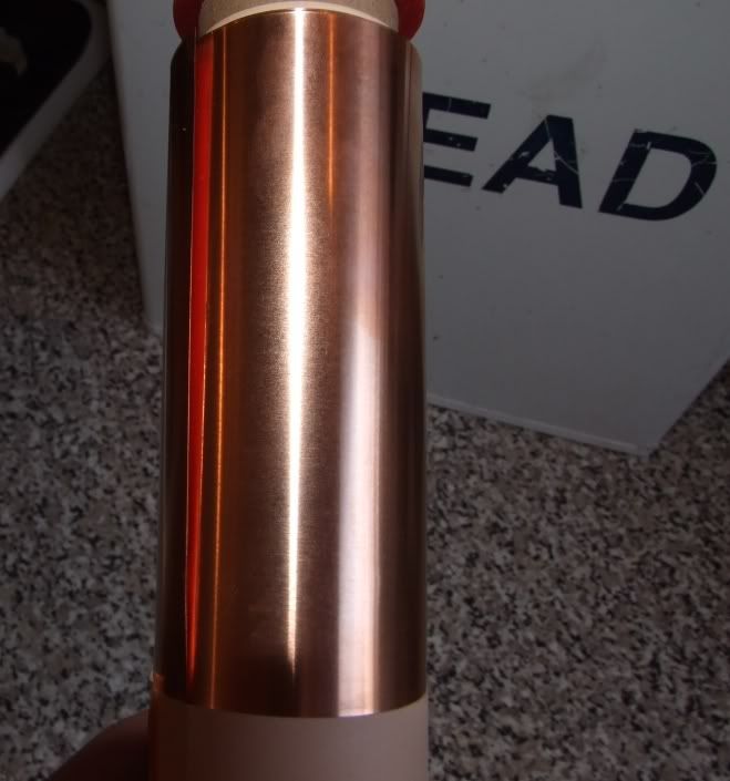
I'd bought a roll of thin copper when I started the project:
PIC OF COPPER ROLL
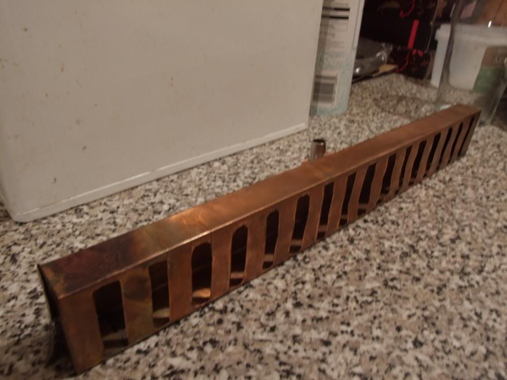
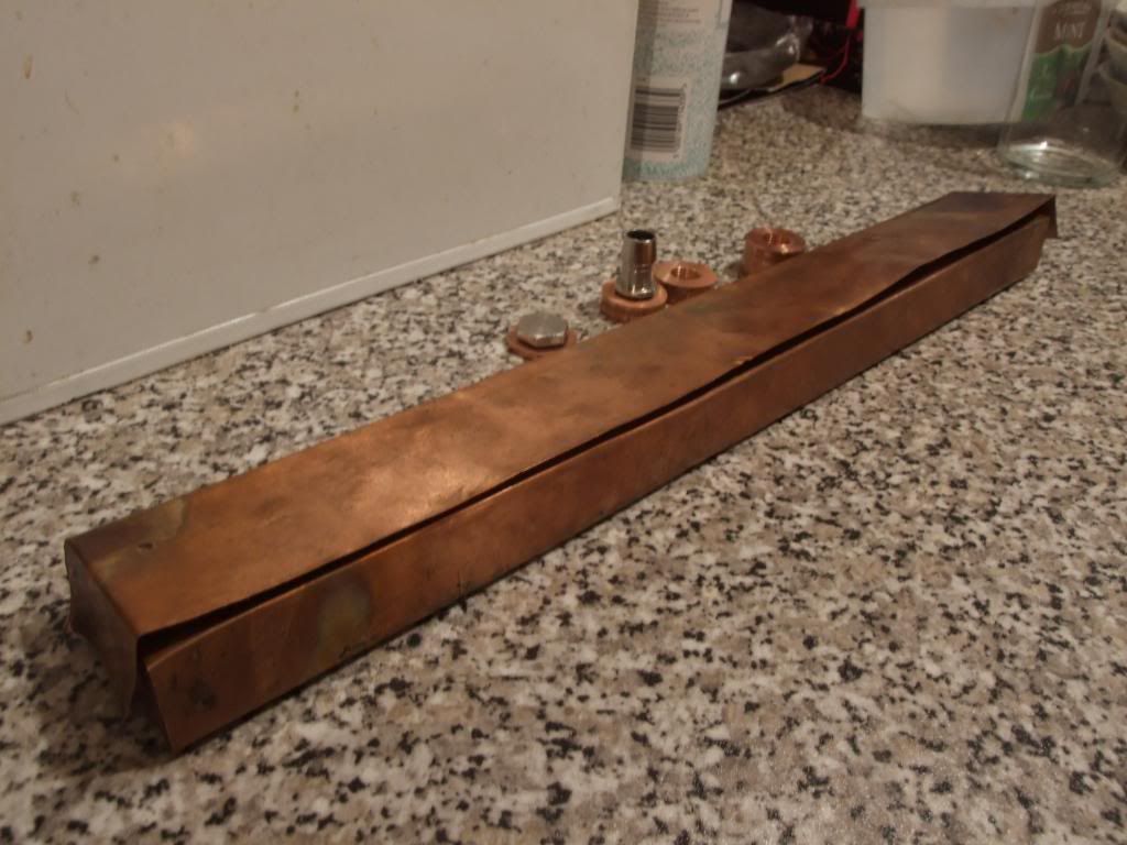
PIC OF ROUGHLY HOW THE BOX WILL GO TOGETHER
The sides look angled and messed up at the moment, since only some of the flaps of copper have been soldered together. I need to be able to open the box at this stage in order to press it against the end-heatfins to make good contact when being soldered to the side of the box with the slits (the pipe ends will protrude through these slits). The rest of the thin-walled box will then be closed up and soldered into place, and reinforcing 0.9mm copper strips soldered to the outside of the box and the inlet, outlet, fillport and drain port soldered on.
Sadly the project will have to take a short hiatus since I'm moving away for work next week and won't be able to take it with me, so finishing it off will have to be done when I can take a week's holiday.
I changed the method by which I put the fins on;- before I had deooxidised the copper pipe prior to putting new fins on, now I instead changed to using strips of 120 grit wet'n'dry with sellotape on the back to strengthen, which I used to sand about 4cm of the pipes, flux and slide fins on (I had already filed the holes of):
PIC OF SANDED PIPES
All the heatfins are now on, and the pipes have been trimmed down.
PICS OF MONSTROSITY
I've decided to make the manifold/plenum from copper - it'll have an inner box made from thin copper (0.152mm thick) joined to the end fin by solder paste, and strengthened with some of the thicker 0.9mm thick copper made from 4 leftover copper strips I had.
My friend Robin has some nice tools and machines, so I asked him to maked the inlet, outlet, fillpoint and drain port for the radiator from the 25mm diameter copper bosses I had.
PIC OF LATHE
After making 11.8mm holes with the lathe the copper bosses were tapped on the lathe with a BSP 1/4 tap, cut with a circular saw mill bit and then fly-cut on the mill to give a beautiful smooth shiny surface, which doesn't really come across in the photos:
MACHINING
PORTS DONE -
I'd bought a roll of thin copper when I started the project:
PIC OF COPPER ROLL
PIC OF ROUGHLY HOW THE BOX WILL GO TOGETHER
The sides look angled and messed up at the moment, since only some of the flaps of copper have been soldered together. I need to be able to open the box at this stage in order to press it against the end-heatfins to make good contact when being soldered to the side of the box with the slits (the pipe ends will protrude through these slits). The rest of the thin-walled box will then be closed up and soldered into place, and reinforcing 0.9mm copper strips soldered to the outside of the box and the inlet, outlet, fillport and drain port soldered on.
Sadly the project will have to take a short hiatus since I'm moving away for work next week and won't be able to take it with me, so finishing it off will have to be done when I can take a week's holiday.


