

normally speaking - I have no experience on the RTX 30 series 12pin adaptor (this is the FE adaptor)This will happen naturally because the wires and connectors have non-zero resistance. There's even some negative feedback because copper has a positive temperature coefficient (hotter wires have more resistance, and so pass a smaller proportion of the current compared to their neighbours).
however say a RTX 3090 has 3 PCIE8 connector - lets call each of these power connector are a circuit and forget about the fact the GPU further split the power into 3/4 phases. so each circuit has its own 12V rail (i know they ultimately all connected to the same rail at PSU but for the purpose of understanding how GPU normally regulate power, lets go along with this). each of these circuit has sense cable to the PSU connecting the GPU to the PSU in terms of power demand.
so a 3090 should be able to demand different about of power from these 3 seperate circuits.
what they have done now with the adaptor seems to be putting everthing on a shared circuit which is confusing. whats the point of 4 sense cable...or even 2 in the case of the adaptor, technically you just need 1 cos all the PSU wants to know is when to delivery 600W on those PCIE8Pins

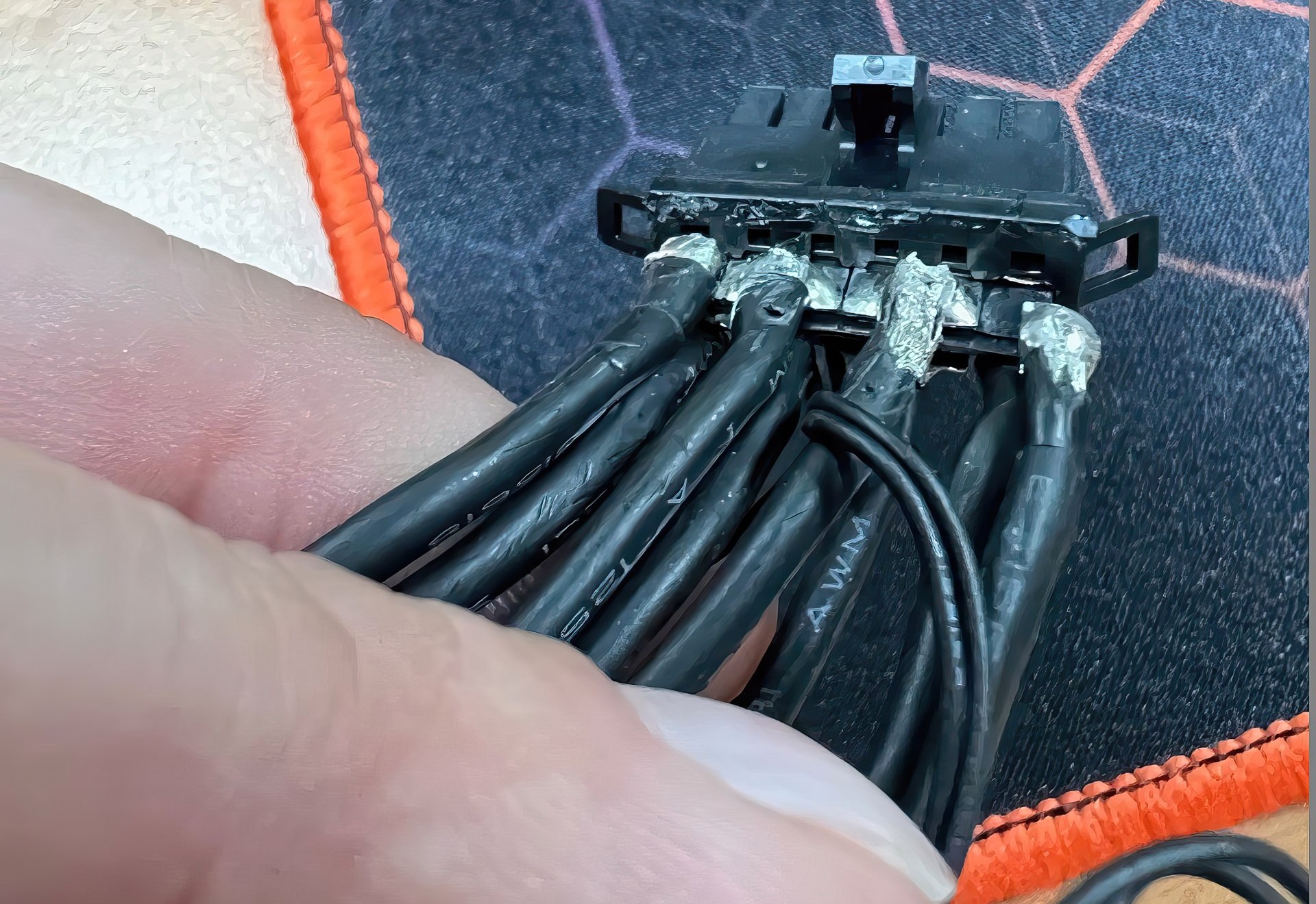
") What i don't get is if there's any reason to do it that way, i mean it seems like there's two redundant pins as like I've been saying i can't see why two of the wires have dedicated pins while another two get split across two pins.
What i don't get is if there's any reason to do it that way, i mean it seems like there's two redundant pins as like I've been saying i can't see why two of the wires have dedicated pins while another two get split across two pins.