• Competitor rules

    Please remember that any mention of competitors, hinting at competitors or offering to provide details of competitors will result in an account suspension. The full rules can be found under the 'Terms and Rules' link in the bottom right corner of your screen. Just don't mention competitors in any way, shape or form and you'll be OK.

Check Your 4090's 12vhpwr Connectors To Make Sure They are in Pristine Condition

Already disproven by Steve at Gamers Nexus

Just another case of Igor being wrong just like he was when 2080ti's were dying and 3090's in new world.

On all 5 of Steve's adaptors no amount of bending was able to break the soldering or even weaken the connection
Wrong, Steve states that he believe what Ignor found is part of the problem but doesn't believe it's "the problem". Therefore nothing is disproven only unconfirmed.
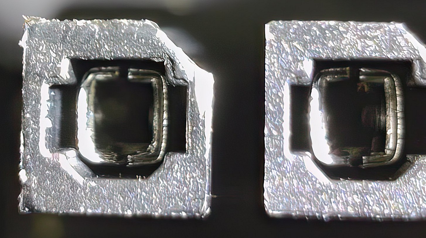
1st off you don't use solder to create a connector like that.
2nd you don't use solder like that when you are using 600watts. Igor is correct.
3rd Steve hasn't provide any proof as to why the issue is happening.
4th Steve tested in an open bench. Not inside of case. I've read no reports of people having this issue on an open bench. At least the majority of issues are in a closed PC Case. Where temps can be pretty toasty. BTW, the inside of my case is no were near that hot.
5th No mention of power cycling the GPU. Because using a atx 2.0 psu cannot properly communicate to the 12vhpwer adapter to even the power draw loads on the 4 pig tails. Therefore, if the gpu is turned on and wants full power when it shouldn't and you do this a few times... What we should be asking is if doing this 30-60 times create melting of the connectors? I've not seen any results of this yet.

You should go back and watch his video again because you are getting a very inaccurate view point on the situation. In particular:
11:57 - We Could Use Your Help!
24:11 - But There is Obviously a Problem
25:07 - Some Native Cables Might Also Fail

Because it's clear he didn't find nor implied that he found the problem nor solution.
 
Last edited:
Already disproven by Steve at Gamers Nexus

Just another case of Igor being wrong just like he was when 2080ti's were dying and 3090's in new world.

On all 5 of Steve's adaptors no amount of bending was able to break the soldering or even weaken the connection
There are a dozen British, EN and ISO standards on cabling and they all agree on one thing: No soldered connections without strain relief.

It is literally cable assembly 101. You never solder joints unless there is proper strain relief. Proper strain relief being a backshell, outer sheath clamping, potting, etc.

Further, terminals with solder connection type usually have a solder cup or some sort of feature to improve the joint. What we're seeing is an ?AWG14? wire soldered to a thin flat piece of plated copper. It's *******. If that came over my desk for a prototype I'd have it remade.

Oh and finally, the reason you don't want solder is you'll end up with massive variation in performance of a mass manufactured part. One might be fine, where another is not. It comes down to where the solder joint boundary is and how many mechanical cycles (transport, use) the part sees. With such a huge piece of wire and a tiny terminal, you're going to have terrible part-to-part consistency.


All this said, for a PC it'll be OK in 99% of cases. You don't get a lot of vibration, unlike a car, aeroplane, rocket, etc. It's just that NV are going to manufacture millions of these, in which case you're going to see the part-to-part consistency issues and it's just bad luck if you're the sucker who's cable/card smokes a bit.
 
Last edited:
why put it back in after to take a pic? shows what? just doesn't want to admit user error.

if it were true they would state it in the original post also


been using it fine for over 2 weeks , almost 3 :D
How would I know? If I had to guess it was to show cable routing to indicate how much strain it had on it.

Not pushing it in is ********, and smacks of hopium on the part of people who believe Nvidia are God's amongst men.
 
How would I know? If I had to guess it was to show cable routing to indicate how much strain it had on it.

Not pushing it in is ********, and smacks of hopium on the part of people who believe Nvidia are God's amongst men.

He's blamed everyone under the sun except the people ultimately resposible for the connector...

:cry:
 
wrong bending doesn't seem to cause anything as seen by multiple users who tried it, if his theory were correct the melting wouldn't be at the tips it would be where the wires enter the plastic around the solder joints.

Maybe some cards are faulty, seem the connectors are full proof according to multiple tests done and videoed on youtube


So why are people being told not to bend the cable until after a certein point if bending does nothing?
 
I think it's simple: the connector is not fit for purpose.

If the cable is susceptible to problems when not at a perfect angle, then it isn't suitable for consumer usage, and needs to be redesigned. There almost certainly won't be enough room in one hell of a lot of cases for the vertical requirement for example. Sounds to me like they should should either added more latches to the plugs, or made it right angled.


Indeed, the connector is very small and the metal connectors inside are very thin, much smaller than 8Pin PCI-E connectors of which there were 2-3 on a card. Each pin and surrounding plastic must be 1/4-1/3 of the size of 8 pin PCIE.

Then you have the weight of the 4 connector dongle hanging off once your PSU cables are plugged into them. I've ensured the weight of the 4 PCI-e's isn't weighted on to the 12 pin.

I do find it odd that some of these 'melted' cables were 'pulled' out as the state of them would lead to being fused together. I guess Igors was carefully cut out maybe.

I was genuinely surprised when seeing how small this connector was in the flesh, pictures of the connector don't do it justice as to how small this 12pin is.
 
Not entirely related but it's a question that's been on my mind for a while: What's the purpose of the 12 pin plug? From what I've seen each of the four 8 pin connectors terminate on the back of the 12pin in a single wire so that means there's 4x2 wires connecting to 12 pins, so why isn't a 8pin PCIe connector used.

Is it some electrical/electronics thing that i don't know about?
 
I'm stuck with a open side panel, just because thr damn adapter is sticking out. I have a Lian Li Lancool 3. Ordered a ROG LOKI 1000w, won't be here till 11th November. Nvidia Forced this connector yet there are no PSUs available atm which support it natively.
 
Not entirely related but it's a question that's been on my mind for a while: What's the purpose of the 12 pin plug? From what I've seen each of the four 8 pin connectors terminate on the back of the 12pin in a single wire so that means there's 4x2 wires connecting to 12 pins, so why isn't a 8pin PCIe connector used.

Is it some electrical/electronics thing that i don't know about?
12VHPWR is a 600w connector which ideally you'd have natively from the PSU. In lieu of that you use the adapter with three or four 150w PCIe 8 pin connectors (for 450w or 600w cards).
 
Not entirely related but it's a question that's been on my mind for a while: What's the purpose of the 12 pin plug? From what I've seen each of the four 8 pin connectors terminate on the back of the 12pin in a single wire so that means there's 4x2 wires connecting to 12 pins, so why isn't a 8pin PCIe connector used.

Is it some electrical/electronics thing that i don't know about?
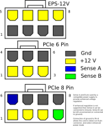
PCIE 8pin has 2 sense cable and the load is distributed into 3 sets of +12V wires. below is the pinout for PCIE 8pin. max power rating for PCIE 8pin cable is 288W meaning each cable carries 8A current.


M3aeL.png
PCIe2.png


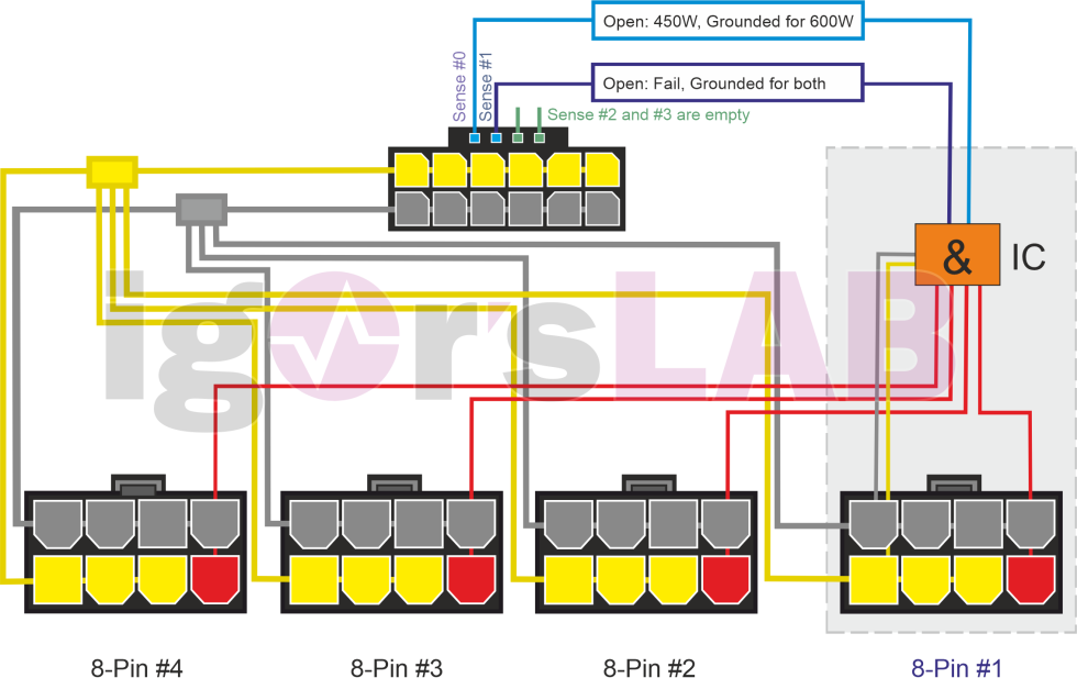
the 16pin connection or 12VHPWER connection has 12pin power and 4 pin sense - power is delivered on 6 sets of pins with a shared bus-bar it seems then the total 600W is distributed over 4xPCIE8 which gives each set of PCIE8 150W. the below is the only diagram seems available as per Igor's invesigation on the wiring of the connector to the PCIE8 pins. so doesnt seem to be that the PCIE8 pin are only having 1 cable going into the 16pin connection - at least that would only fullfill 4 sets of the 6 sets of +12V power pin and its assocaited ground.
Adapter-Scheme-Web-4-980x617.png


tehcnically you can easily deliver 600W power on 3 PCIE8 pin - in corsairs adaptor case, it is delivered via 2 pcie8 pin - one pressume the cable gauge is significantly increased for that purpose. it makes total sense for 2 pcie8 pin to the new 16pin connection as each cable is a direct pin to pin connection to the new 16pin
 
Last edited:
Already disproven by Steve at Gamers Nexus

Just another case of Igor being wrong just like he was when 2080ti's were dying and 3090's in new world.

On all 5 of Steve's adaptors no amount of bending was able to break the soldering or even weaken the connection

Lots of people grasping at straws right now to solve the mystery. If it were as simple as a connector issue Nvidia would have most likely send something. More likely its related to uneven load distribution across the 6 12v pins if they arn't electrically connected
at the connector. I'm guessing they arn't, which is why the sense pins exist. Anyone with a multimeter/voltmeter and a 4090 could check this easily enough.
 
@pc-guy and Surveyor. Thanks for the replies however, and obviously it's my fault for not explaining properly, you're both telling my stuff i already knew, so I'll try to make my question make more sense. :)

So a standard 8pin connector has 3 power pins (+&- for a total of 6) and 2x sense pins, when plugged into the adaptor each of those get reduced to single wires and when all four are plugged in you've basically got 4 power wires (+&- for a total of 8) and 4 sense wires. Essentially we connect each 8 pin PCIe connector to a single wire pair and then connect those 4 wire pairs (4x8 +&-) to 12 pins, so why not just connect those 4 wire pairs (plus the sense wires) to another 8pin PCIe connector with the sense wires connected to the sense connector.

E.g Using the lower image you posted from Igor, pc-guy, the yellow and grey boxes to the left of the 12pin have 4 wires going into them, one from each of the 4 x 8 pin PCIe connectors (and that's what the actual images show) so why not have a 8pin PCIe connector where those yellow and grey boxes are, why terminate 4 wire pairs (8 in total) on 12 pins, why not just terminate them on 8 pins.
 
Last edited:
@pc-guy and Surveyor. Thanks for the replies however, and obviously it's my fault for not explaining properly, you're both telling my stuff i already knew, so I'll try to make my question make more sense. :)

So a standard 8pin connector has 3 power pins (+&- for a total of 6) and 2x sense pins, when plugged into the adaptor each of those get reduced to single wires and when all four are plugged in you've basically got 4 power wires (+&- for a total of 8) and 4 sense wires. Essentially we connect each 8 pin PCIe connector to a single wire pair and then connect those 4 wire pairs (4x8 +&-) to 12 pins, so why not just connect those 4 wire pairs (plus the sense wires) to another 8pin PCIe connector with the sense wires connected to the sense connector.

E.g Using the lower image you posted from Igor, pc-guy, the yellow and grey boxes to the left of the 12pin have 4 wires going into them, one from each of the 4 x 8 pin PCIe connectors (and that's what the actual images show) so why not have a 8pin PCIe connector where those yellow and grey boxes are, why terminate 4 wire pairs (8 in total) on 12 pins, why not just terminate them on 8 pins.
the new connector is 16PIN not 12PIN.

there are 12 power pins and 4 sense pins. the way it works is that the 16pin connector somehow average the load across allt he PCIE8pin connectors. I am not sure how it manages it as everything I know about power cables tells me that is such a bad idea.

if you look at Igor's diagram, the 4 pins sense is smaller format above the 12pin power

both Bequiet and Corsair has take the approach of using 2 PCIE PSU end connection to power 600W 12VHPWR (16PIN) connector.


it is so interesting to see there is a clear divergence of standard for the new connector. or rather lack of unified standard the backward compatibility.

pulling 300W out of a PSU single VGA port is quite dangerous in all fairness - I have see PSU connector at the PSU end melt etc so not entirely sure what is going on there. personally I would go for a 3 PCIE 8pin solution rather than 2 or 4. 3 PCIE 8pin (given you are not using daisy chain pcie cable) should easily manage the 600W load. the cables and plastics are all rated for 288W at max 200W load per cable, it will be safe.
 
Last edited:
...the 16pin connector somehow average the load across allt he PCIE8pin connectors...
This will happen naturally because the wires and connectors have non-zero resistance. There's even some negative feedback because copper has a positive temperature coefficient (hotter wires have more resistance, and so pass a smaller proportion of the current compared to their neighbours).
 
Well Igor quickly changed his mind

Now he believes the problem is user error, people incorrectly connecting the cable

"Of course, today’s tests are only snapshots and the conclusion that you always look for a small edge somewhere to put on and insert may well be true in its statement. The design and manufacturing defects found on the plug, the drama during bending including the resulting mechanically damaged contacts are only one side. The error pattern as a whole is now far too complex to be able to determine 100% what the primary trigger was for whom and which adapter."

i am not sure i agree with him on that statement. there might be a design issue with the adaptor. but certainly nothing points to manufacturing defect. if there is a manufacturing defect there will be much more cases coming out.

Igor likes his sweeping statements unfortunately.

GN being very diplomatic when Steve did his video, but you can sense the undertone is that Igor jumped to conclusions.
 
Back
Top Bottom