OCUK Official IC Diamond/ Perihelion Test Results

Posted:)

Let me know again when you have received it


After some thought I decided to conduct the lapped testing in June which is meant to be one of the hottest month in UK. It will be ideal time.

Lapped testing methodology will be similar to unlapped testing :cool:

received it today perhaps results by the end of the week
 
IC Diamond

I forgot to mention earlier that with regards to 'close to contact' margins and looking at the general contact profile, I also felt that the gap between IFX-14 and Q6600 surfaces is very very small indeed. Even the area where there is hardly much contact, we can still see tiny spots or 'mole hills'. So there is contact there but it is just a 'touch'.

1 mil is 1/1000 of an inch or 0.0254mm.

So 0.0005mil = 0.0005 x 0.0254 = 0.0000127mm

It is astonishing that a very very tiny fraction of a mm can make all the difference:eek:.

Could it be that while lapping, some of the grit particles managed to get stuck into the Cpu IHs or heatsink base, thus preventing any further contact?

What would you suggest?

In my lapping experience the only sandpaper I have found most effective in shaving the metal is 120 grit.

I would not worry about the grit.

Key thing to remember - increased contact does not increase pressure, but generally increased pressure will increase contact. Pressure is the more dominant of the two.

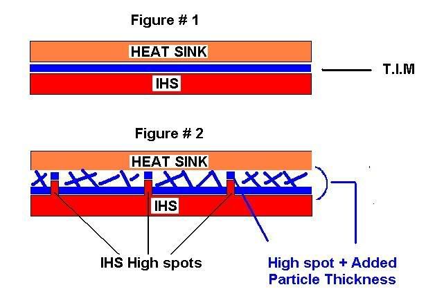
Let's flip the problem, In engineering a common device used to limit heat flow to sensitive components in an assembly is a “Heat Dam” shown here in figure #3 Where the heat flow is “thermally choked” by reducing the contact area to material limitations. Restricted heat flows with misaligned contact, too little contact, too little pressure, too little compound anything that can restrict flow creates a heat dam.

Heat flows on a differential from hot to cold but if you are thermally choked at a point in the thermal cascade downstream improvements in thermal conductivity offers little difference in performance and shows up as reduced deltas of only a degree or so between compounds or what I sometimes refer to as homogenized test results.

Now back to your situation, your analysis of having contact in the right area is correct rather than forcing the heat flow across the IHS to the sink which is a thermally choked condition pushing to the material limit of the copper. I believe the molehill change from mountain allows a thermal compound to work as designed now by being able to bridge the gap from IHS to sink as in Figure 1. These are the thresholds or tipping points for you guys and all your ducks need to lined up in detail to squeeze the most out of your systems.

For further improvement possibly a degree or two from improved contact and another 1-2 from increased pressure although I lean towards more pressure at this point.

If you could figure a shim to tighten down the sink some more...


heat_dam.png
 
Last edited:
Nice insight :)


Edit: Would washers do the job aswell if I placed one or two between the mounting plate and the top surface of heatsink base as showed in post 291:

applicationofifx14mount.png

Application of Mounting System

I believe you are onto it. Just a matter of taking up the slack realized from the base material loss and a shim under the mounting plate center would do it, perhaps a coin or a few layers of duct tape
 
I would like the info so I will send you some more. Your anomaly of light pressure, light contact, improved thermal adds to our library of results while it's always about contact and pressure there are gradiations in between that are always not easily explainable so the addition will add depth to our troubleshooting efforts.

Nice work, good analysis btw - have to summarize all the results makes a great article
 
mx4 ICD 1 ICD2
73 74 74
79 80 80
77 79 79
77 77 78

Avgerage 76.5 77.5 77.75

Ambient 23.5 24.7 26

Temp rise above ambient 53 52.8 51.75

Have to subtract ambient so ICD - 0.2 C first run , -1.25 C 2nd run
 
IC Diamond 24 is just a waste of money ! MX4 is the best thermal paste and I can see here it not much the different between MX4 and ICD 24. So, paying an extra fiver for ICD 24 is just silly to be honest !

So let's put it to the test with a shoot out between the two

I'll put up the IC Diamond and if I can come to a reasonable arrangement with OCUK for a couple hundred tubes I'll pay for the MX-4 - we can test fro both performance and reliability.

I have been thinking of changing the format and going one to one from here on out this would be a great test if we can get enough people to participate..

I will even add a contact and pressure test kit with each sample, lab analysis is to expensive but Raw prints will reveal a lot and be comparable to IC library of image analysis to date
 
Last edited:
I do agree with you +1

Personally I think the whole bowed base concept is to edgy "if" it is a viable tweak to hit an optimum point you are relying on too many uncontrollable variables with IHS contour and hardware mounting inconsistencies.

With the two lapped examples we a 5C and a 7C improvement - the first high end sink manufacturer that incorporated it would kill the competition.

I think it is most likely a manufacturing issue as noted earlier - the base is warped on heat assembly and the final assembly is too awkward to machine flat.
 
Right so about time I tested this too. Received tubes quite a while ago. Replacing my Titan Fenrir with the Antec Kuhler H2O 620.

Tested with Arctic Silver 5 now for IC Diamond.

What is the best way to apply IC Diamond? With AS5 I applied small pea sized amount to CPU and spread with plastic credit card.

I used it on my HTPC but found that using the spread method was difficult because of the thick viscosity of the paste and abandoned it and went for AS5.

Application Notes -Amount of Applied Compound - FAQ
*
*
There is always some debate on amount of applied compound to use, our approach is based on a best to worst case scenario with a one size fits all so the user can experience best odds of a successful mount out of the gate without having to redo his mount.
*
*
Say that Intel has a spec of Flat and parallel // to .002. - At the extreme end you get something like the 2 images of the candidate below, to fill that gap/volume you need .05 ml volume of compound for a 30mm X 30mm area about the size of a grain of rice.
*
worstcase1.png
worstcase2.png

*
Our difference with the rice method comes from the other side of the equation The heat sink base, while many HS bases are good some can be off as much as the IHS and to cover the contingency of irregular contour on both sink & IHS and as few people lap to correct the problem (5%?)and fewer lap to perfection so we add another .05 ml for a total of 0.1ml.
*
Another factor associated with irregular contours is another mil or two layer of compound is added on the high spots depending on the pressure applied. To fill that gap we add another .05 ml for a total recommended amount of 0.15 ml which approx. equals our 5-5.5mm size bead on center.

IF YOU ARE NOT SURE PEEL BACK THE LABEL TO SEE ML REGISTRATION MARKS AND USE 0.15-2ml EXCESS JUST SQUISHES OUT - I HAVE MEASURED THIS WITH A MICROMETER @ 50 PSI AND AT ROOM TEMP YOU REACH 95% OF THE BOND-LINE THICKNESS (BLT) IN TWO HOURS 99% OR MAYBE 1/2 DEGREE OVERNIGHT AFTER THE INITIAL 2 HOURS
*
Thermal compound is a volume application to fill gaps, not one of weight, liquid spread-ability etc. and our opinion is that whatever the compound you still need the equivalent volume to close that gap.
*
Flatnessnote.jpg

*
Additionally it is important to apply enough compound, because as the paste thins it spreads it reaches a maximum zone where air is reformed into the paste application between the sink and his leading to decreased performance and early compound failure. This effect is well-documented and known as Laplacian Growth AKA cusp formation and viscous fingering.

Fast Simulation of Laplacian Growth

http://www.youtube.com/embed/AHmgPtOJsYk
Laplacian Growth in thermal compounds

lineclamped.JPG


3.JPG


Laplacian Growth - a good visual explanation

http://www.physics.ubc.ca/pitp/archives/theory/2004talks/wiegmann.pdf


http://innovationcooling.com/applicationinstructions.htm
 
i7 920 @ 4.2Ghz with 1.34 volts and 1.32VTT
EK Supreme HF Copper
2 x Thermochill PA 120.3s

Original compound was MX-2
All tests were 15min of LinX 4900mb memory used

** Application method was the cross method (see below) **

Before Compound:
Ambient Temp: 19
Idle Temp: 31
Load Temp: 64

ICD 24
Ambient Temp: 20
Idle Temp: 33
Load Temp: 63.5

During my first test I saw that the IC diamond 24 was >1c higher than the MX-2 under load even after > 8 hours cure time. I realised that this could well be because my MX-2 application method had been the cross approach. I reapplied the Diamond in the cross pattern and got the results above.

The diamond is a very thick paste that is tricky to apply to the IHS. This could be the reason why the pea method produced weaker results. MX-2 spreads easier from my experiance.


**EDIT**

The difficulty in spreading with the pea method with IC Diamond 24 could be to do with the EK Supreme's poor mounting mechanism

Read post http://forums.overclockers.co.uk/showpost.php?p=19331977&postcount=408

Thermally choked would be my guess - If the contact is spotty or the pressure is light or some combination of the two the results can be dominated to such an extent that it overrides the other variables in the thermal cascade so paste 1,2,3 measure only a degree or two difference.

as in the discussion on the previous page picture the block making contact with the IHS but not in areas where the core (s) are located, so the heat has to travel some distance across the IHS now the material resistance is maxed out as the IHS is of inadequate thickness to transfer the heat properly.

In heat sink design to get the heat to spread efficiently a base thickness of .160 inches is required for copper. More material generally does not add anything but less material and performance drops significantly @ .140 inches you can lose 2-3C and the sink becomes thermally choked. With an IHS you have much less material to spread heat and so the thermal resistance is so high that it dominates the result.

As an example of one factor dominating a result - in axial fan design for computers you have several sources of noise, bearing, tip vortices's, blade pass over the struts etc.

Tip vortices's being the loudest are the dominant source for noise. In fan design if you want to reduce noise it is not worth the effort to reduce secondary sources because the dominant tip vortex noise will still be X dBA. Reduce the tip noise and the secondary factors emerge from the background and can nowbe treated for noise reduction.

Same with the IHS thermal resistance as dominate other effects are masked.

the EK Supreme along with the Corsair seemed to be trending better than the other waterblocks.

I would really like to get some contact and pressure tests on some waterblocks, would you be interested in running some contact and pressure tests on your block? I'll send you a test kit.
 
F
an speeds
In the Post 291 I gave a general outline of fan speeds during idle and load. We also saw that fans never spin at the same speed and that there is always some give or take fan rotations from the average fan speed. Although this shouldn't affect the performance as the loading is same; nonetheless this factor can't be ignored.

In your fan test was that for all compounds or just a general fan evaluation? PWM Disabled for all tests?

One thought is that straddling a set point on temperature fan speed could ramp up or down between compound tests with a couple of degrees difference.

Pressure is at the threshold around 50 PSI, that in conjunction with a 3 day cure which implies a low pressure - I usually do not see any cure times I generally test between 60 and 90 PSI and mostly around 90 which gets me to the BLT fairly quickly so I do not have to wait long for a result when I am impatient.

I have mic'ed it with a couple of glass slides and synthetic IHS @ 60 PSI and I usually get 95 -98% of the bond line thickness in about 2hours @ around 20C ambient, overnight at that pressure yields another 1/2 C at most. A little higher heat, 30 to 50C should enhance the spread quite a bit & people regularly report cure times higher but they are usually sub 50 C an off optimum point. 2 C seems like a lot to me but at the threshold there I would expect an improvement with added pressure in cure time and overall number. Thinner compounds do reach the bond line at much lower pressures so usually see little improvement with added force as they are as far as they can go compression wise.
 
It was a general fan evaluation to try to gain a better insight on fan speeds. Only the Akasa Viper fans and the front 140mm fan are in PWM.
The rest of the fans are spinning at full speed and even then it can be seen that there is some fluctuation in the speeds during idle and load.


For the Washer Modded testing I will disable PWM to see if that has any impact on the test results;so Akasa Vipers and 140mm front fan will also be spinning at full speed at idle and load:)

Generally you have some pulsing of flow in a stable situation, about 5% is usually what I figure for an average max.

Most influential would be the heat sink fans if modulation kicked in @ a 10-20% RPM reduction raising the CPU temp a degree or 2 so test runs on before and after are not directly comparable.

I tried on a couple of giveaways to get end users to disable PWM or at least note fan speeds for fan law correction later as ICD loses most I believe when it occurs but the more complex the testing the less data I get so maybe response was about 10% on the request. Like herding cats sometimes...

So if a bias exists there or not it just gets averaged in with the rest of the data.
 
It helps to be among the more paranoid when testing just about anything, you test from any vantage point forward and backward, upside down and Sundays, high resolution is critical as well as a keen eye for observation, varying test parameters to get details to emerge that can be leveraged to your advantage.

I have had moments in fan design when I thought I had made breakthroughs only to find out the airflow chamber under certain conditions created a recirculating flow that screwed up the measurement or when measuring fan noise a sound wave bounce off the floor at 1 meter intersected with the wave straight from the source creating a noise cancellation effect. Best to be a little humble and and a little nervous for the serious testing.

As noted before before the closer you get to optimum the more unstable things become. For example take a 25 cm high bar that is 4cm on a side and stand it upright on a perfectly level surface plate,reasonably stable at this point. Now reduce the the 4 cm dim to 2 cm or one cm or perhaps a 1/2 cm as some point other factors become critical,, a low or high spot on the plate, perhaps only a few millionths of an inch cause it to become unstable and fall over,vibration from a passing car or a
foot step or an immeasurable incline in the setup can cause failure to stand.

These PC platforms have all kinds of tolerance issues, Stacked mechanical tolerances probably of +/- .005 on each piece of mounting hardware, board thickness, unbalanced mounts, board flex etc.

I think a liberal view would be to say most here measured within +/- 2 C on their ambient maybe +/- 1 C on their thermal sensors along with factors of fan speed, air recirculation, amount of compound used, contact, pressure with software variables, age of compounds, cleanliness of the setup...

So no one test is perfect as in this format I can say things like 80% saw an average improvement of X y or z it balances out with a 95% confidence.

When I test competitors compounds I never average multiple tests as I think it introduces a bias on my part, I always take the better number for comparison because it usually means I have it working as it should and not at some lessor number where I had an error in the setup.

IC Perihelion - I am struggling with a bit, on the last German giveaway in which I had no forum participation we had approx 90 returns and was only on average 1 C off the IC Diamond averages although we 17 no results for the Perihelion out of the 90 whereas for IC Diamond we only had 1 no result out of 126 tests. The Perihelion even with the high no result number was second only to IC Diamond. From my own tests I know it,s a great compeitor.

While measured viscosity is exactly the same as IC Diamond and the chemical make up is nearly identical except for aluminum oxide over diamond it's physical characteristics are different and responds better under better contact and pressure. It may be that another application method would be better although I would hate to have to resort to something like a spatula type spreading.

What's interesting from a marketing point is that some make a rough equivalent argument of a couple of C between compounds or cost savings yet most here expressed little interest in it and in countries where per capita is only $3,000 a year and IC Diamond 24 is offered for purchase in 10 easy payments
it still sells better than the Perihelion in retail and at nearly the same volumes that I get out of equivalent US or Euro online retail stores although Perihelion is twice IC Diamond sale in those repair and SI markets.

One thing I have learnt so far in carrying out the testing is that the experimental results to some extent betray your preconceived idea of how the results will turn out even if they contain some form of human error.

I always learn something from these tests

7mm - probably need less when pressure increases
 
Last edited:
About averaging - I test on a lapped synthetic die and sink with 93% area contact and usually @ 90+ psi with metered power supplies for fans and heat source I can measure temps to a 1/100 of a degree, watts to a tenth, open bench 10 thermocouples. I know how much power going in and how much is being dissipated, digital tach with fan speed controlled to less than 2% , I have thermocouples located through the sink and die so I can measure the temp drop across the compound etc.

The parameters of the test are pretty disciplined with variations of less than .5C between mounts, occasionally a mount might be biased or paste separated or at lowered temps and pressure the compound may not have settled completely, in any event my setup is generally optimized for the testing of any compound with high pressures and good contact. (Much easier to work with than your set up)I do not have to worry about where I am on a thermal/pressure performance curve. In other words the setup pretty stable but if I get a variation of a degree I will take the better number.

In your setup/test series you have number of rotating parameters, low contact, high pressure or low pressure, high contact which would not be comparable results and easy to readily observe several degrees between tests

To qualify a result you have to quantify it. All paste thermal vs pressure curves are different, so where are you on this curve below? Where are you on the comparison compound curve ?

pastepressure.jpg


I have seen some compounds flatline at 30 psi @ their average particle size or optimum BLT a comparison paste might hit the same point @ 40 psi which is ok in a test series as long as you quantify it with something like "screws were torqued to x number of inch oz. or surfaces were machined lapped to within .0002" Now you pull both thermal performance curves and you can say now that under these conditions I have these results which are qualified because they were quantified and may be or maybe not line up on the idealized curve but they are at least qualified as data.

An extreme comparison might be a liquid metal that probably hits it's BLT @ 10 psi barely enough to hold the sink on now compare at the same mounting pressure compounds that do not hit their stride until 40-50 psi as an extreme you will see 10C + advantage for the Liquid Metal (LM) not to say the LM is not good just the comparison result is greatly exaggerated and the result is not quantified so is not a qualified result. LM pads can give a great result on a lapped sink but get some irregular contours and if you notice LM pads are very thin and do not bridge gaps well and will test poorly against comparison compounds under those conditions. Details are a requirement for serious testing, absence of detail end in a murky understanding of the final result when your test tolerance is several degrees and your comparison measurement is under the range of error.

Heat flows on a differential so a condition can arise where if the CPU is 30 C hotter than the MB it will pump heat/Watts to the MB or in watercooling or TEC's the temp can be lower than the MB and draw heat in the other direction. It's common practice to set up controlled thermal environments for tests by isolating components with water blocks on opposite sides to normalize heat flows or to test in wind tunnels with controlled airflow and temperatures. Kind of concentric circles of Dante's hell in a fractual or chaotic sense. I have seen engineers chase their tails with minutia for years, you always have to have the bigger picture in mind but aware of the detail significance. Only lightly touching the surface here more variables than you can shake a stick at :)

Modeling and testing air and heat flows is non trivial and back in the day a few years ago OEM's quoted to me their expense of about 3-$400k to do you basic box cooling to harmonize airflow,noise and thermals and double that for a high end workstation.

My testing aside what really counts is what the boots on the ground see on their desktop screen and fortunately there are other ways to skin a cat for accuracy, statistics have been around for hundreds of years vetted by the world greatest mathematicians, good mount bad mount, high and low airflow, varying power etc all the countless known and unknown variables get averaged in, even the biases
 
Last edited:
Sensor products introduced a new paper this year so you should compare to the OCUK review sample. A little different than the older stuff so I am not always sure what I am looking at on a screen shot. May be the light or camera but the first test looks better than the second deeper red (higher pressure) + more contact area.

Pressure does dominate as increased pressure increased contact into a more defined pattern than pre washer raw image.

Looking at he two impressions looks like the hardware has a slight bias to heavier on the left and a little light on the right. Might rotate the bracket to see if it corrects.

rawimga.jpg
statisticsa.jpg

lapping2.png
imag0239s.jpg
 
Perhaps it is the silly season and parsing things to a too fine detail.

May or may not make a difference you are down to things like perhaps the mother board is a little thicker in one side or the stamped and bent brackets between the two ends are off .010 - Tolerance on this stuff is probably +/- .005 and with some tolerance stacking in the assembly, my guess it's pretty hit or miss whether you get an almost perfect contact like the OCUK review lapping job above or some unbalancing where one side might have 80 PSI and the other side 40 psi or even "0.0" psi

You could try a shim on the high side, maybe a piece of duct tape would do it.

all in all you have a pretty broad contact pattern which compensates a lot for misalignments even if the sink is a few thousandths higher on one end than the other.

It is more of an issue perhaps in cases like the bowed water blocks which start with a narrow contact area on center (<50%? of IHS contact area ) to begin with so along the contact axis only maybe 1/4 of the the IHS on one side would be would be in full contact with the sink so the setup would be pretty well thermally choked.

My guess is you would see an unbalance to some extent in most bowed configurations.
 
Last edited:
I'll send some more - nontrivial as they say..

I am thinking there must be a poor man's way of doing this - maybe carbon paper between two pieces of paper

or

a rubbing impression like they do on old gravestones

or

Perhaps a colored wax - turn the machine on for a minute low spots would be colored and high or contact areas would have a clear translucent glaze.

You have done a few of these tests and you can transfer that experience by observing paste impressions and comparing them to the sensor product prints - take some pictures then compare much in common just a little different view of it.

Take a cheap compound and do a few mounts, optimize it some more while you are waiting for the paper.
 
Back
Top Bottom