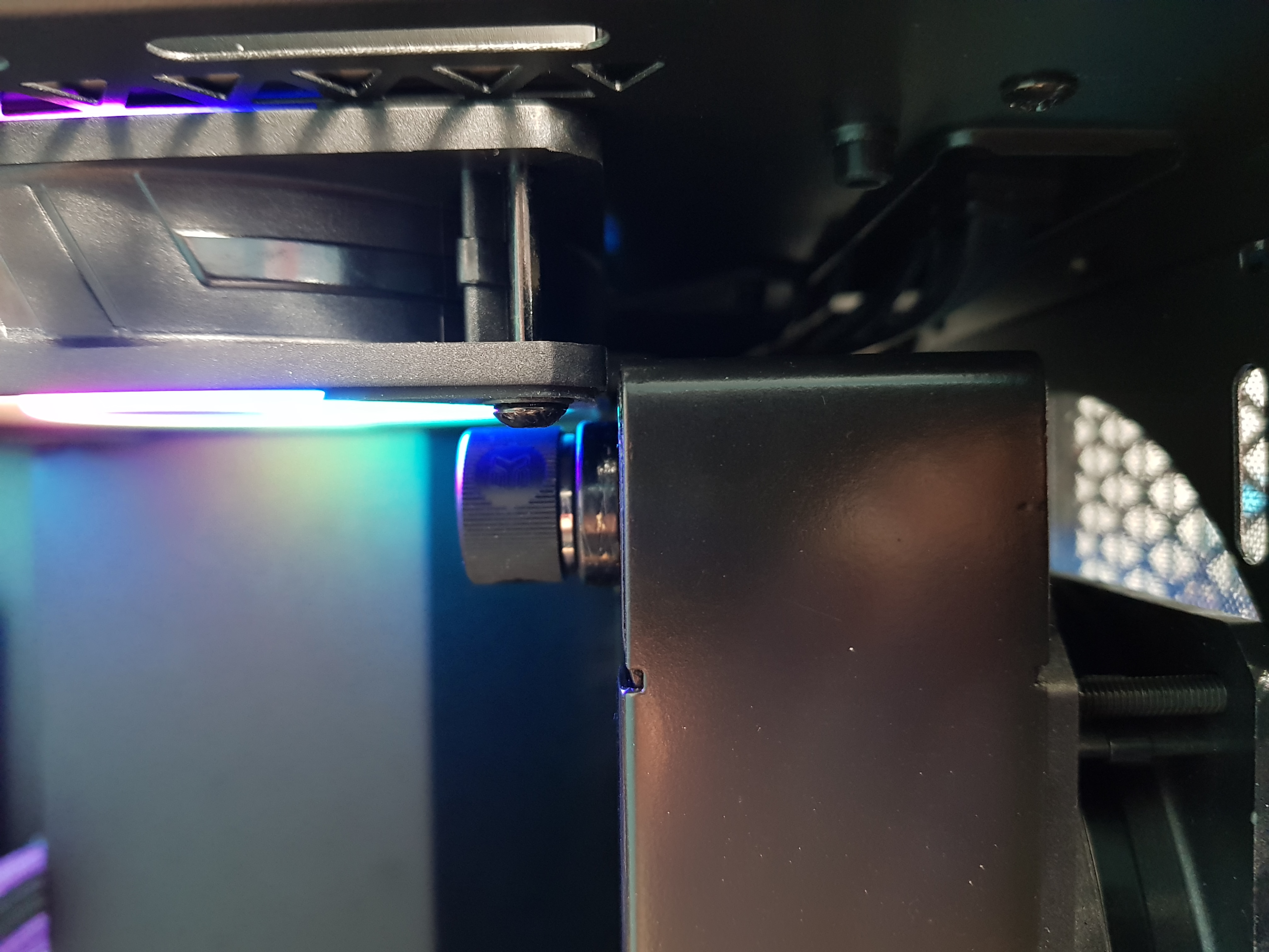
ARGB LEDs arrived

They look just like normal RGB LEDs....suspiciously so in fact. Perhaps I'm just getting (more) cynical in my old age! But after some jury-rigged breadboarding, some colourful language and shouting "Yee Haw!" a bit (because cowboy'ing it) they work!
You have four pins on an ARGB LED....yes, four...no, not three like you might expect. Those are 5V, Ground, data IN and data OUT. You can chain the 'out' of one to the 'in' of the next.
I also understand about splitting ARGB lines and how to make a Farbwerk 360 do my bidding!
If you continue a string of LEDs - such as connecting the 'OUT' port of an 15-LED Aqua Computer RGBpx strip to the 'IN' port of the next strip, they continue sequentially; like one longer 30-LED strip. The same principle applies for the singles if you chain out to in.
If instead, you split the connection before the strip and connect the channel to two strips in parallel, the act like clones of each other with LEDs 1-15 on each. This would work quite nicely for fans and RAM where you want them to be doing the same thing. Not so useful if you want them to do different things. On to channels and it'll make sense in a minute.
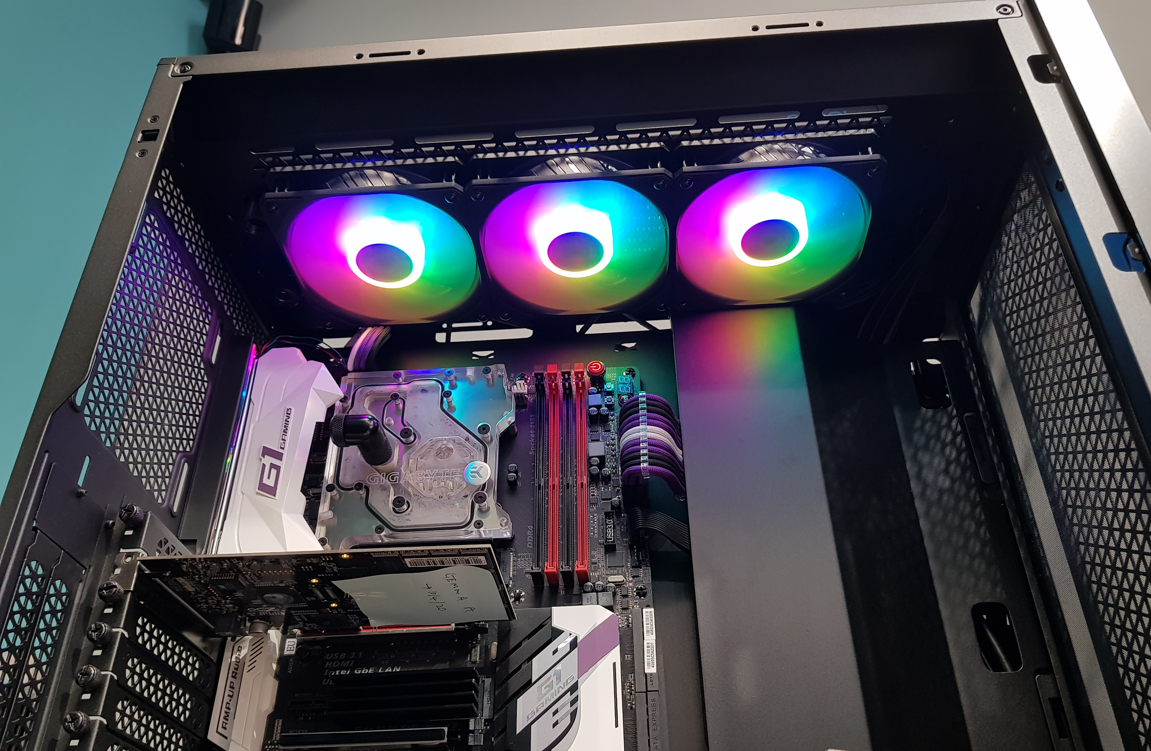
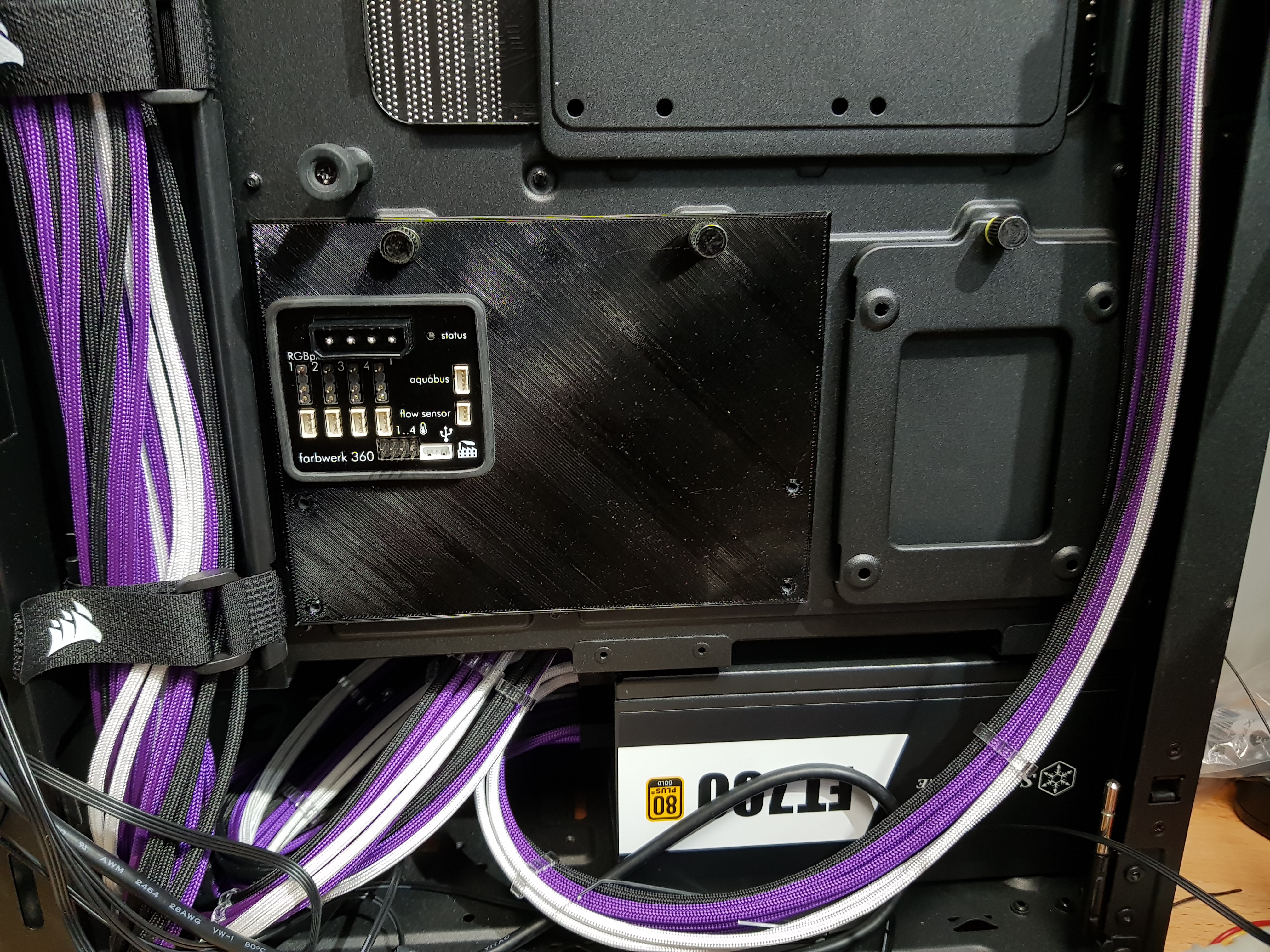
So there are four channels on the Farbwerk 360 and you can have up to 90 LEDs per channel. While there are initially two controllers set for each channel, you can assign just one or a bunch of them. The key thing that isn't immediately obvious is that you can shrink the size of a controller so that it only covers say two LEDs and then drag it about to select which two you want...and then name it so you don't get confused. Why is this important? Well, put the two together and it means I can run one channel from the Farbwerk to the first LED on the CPU block, then on to the second and then on to the first and second LEDs in the GPU block. No resistors required and I can address each of them separately - or, in this case, in pairs.
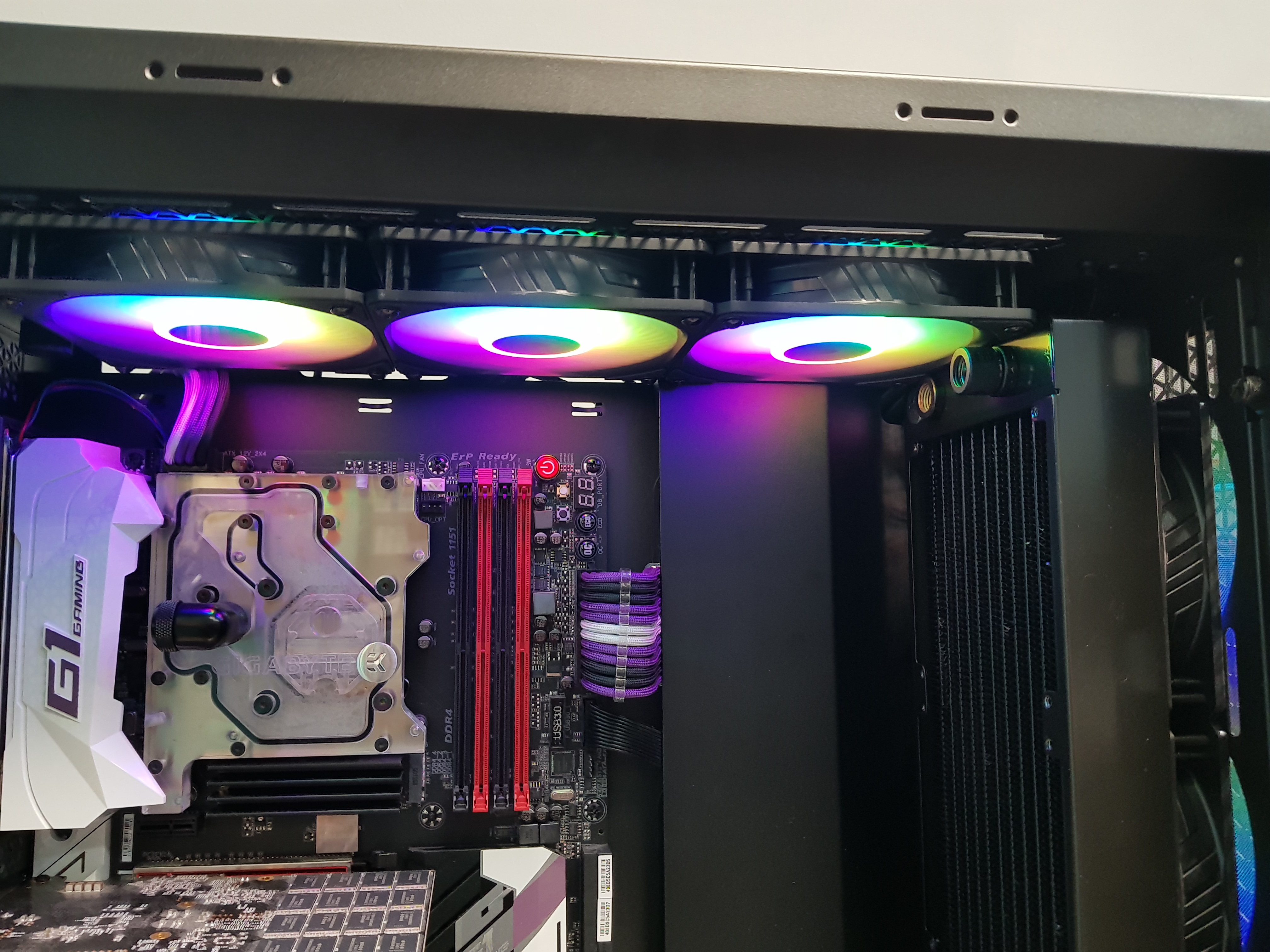
The RGB is - unless I've missed something...which is very possible! - only for the CPU block and the GPU block.
You could see the foreshadowing, right? Well, in comes my son and says "What about the RAM lighting?"....and yup, that's RGB rather than ARGB. So I looked at completely new ARGB RAM....but it all requires specific software to drive it and isn't compatible with the Farbwerk as a controller....and I want to have just one controller for the lot. I'm awkward and demanding like that!
So I looked at new ARGB RAM heatsinks. The
Jonsbo NC1 that OCUK has (cheaper than anyone else, I might add!) aren't bad looking and only £8, I'll have those.....oh, hang on that's a single and I'll need four. Hmmm, more than I want to pay to make the RAM look 'pretty' - especially when for just over twice that, you can have new sticks of DDR4 with them pre-attached! So I started taking the heat spreaders I had apart to see what's in them. It turns out that it's very dismantle'able and contains a small 4mm wide PCB with RGB LEDs on it. So I've ordered ½m of 4mm wide ARGB tape that I reckon I can jam in there instead. Total cost? A fiver.
Next on the list is the connections.
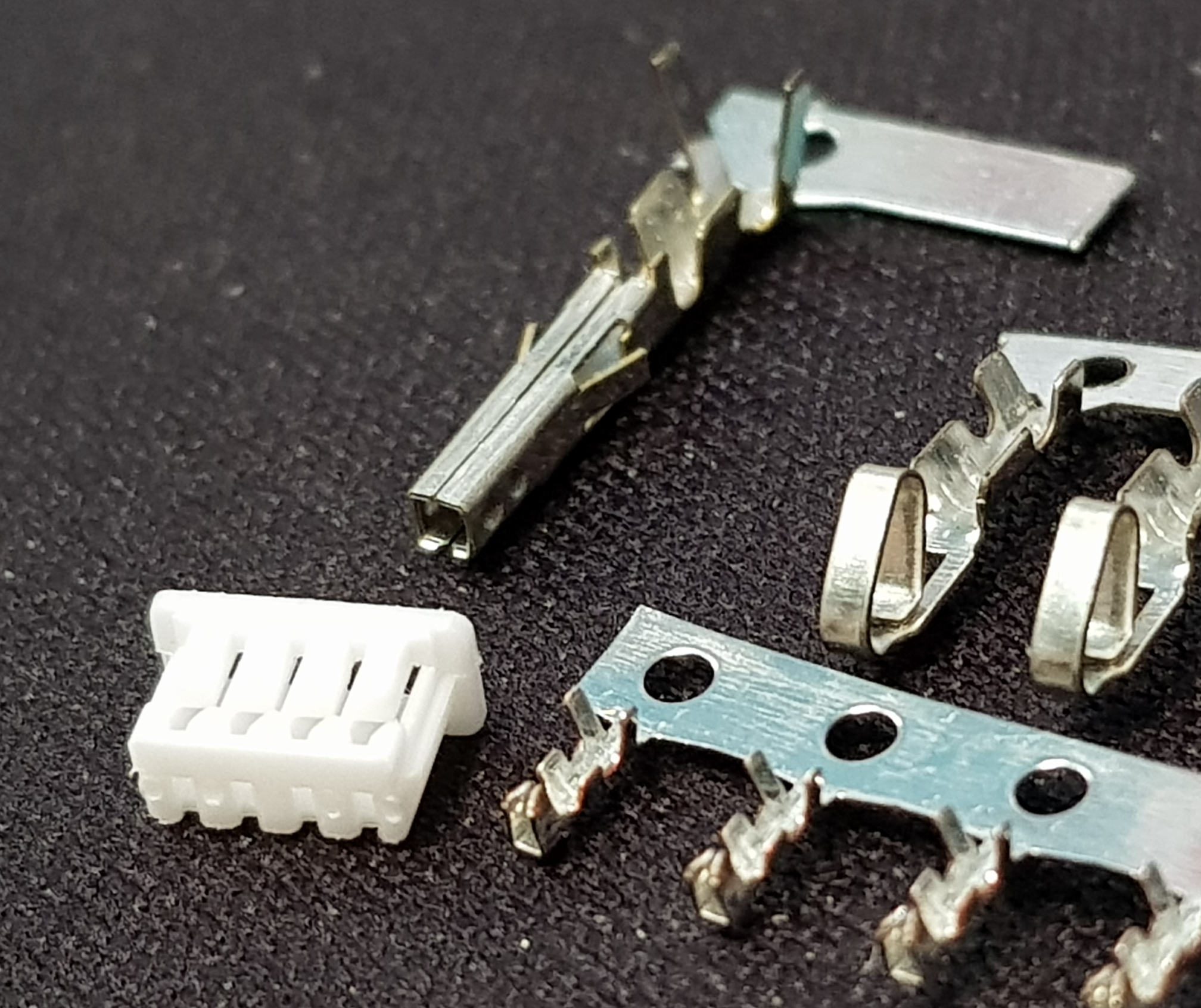
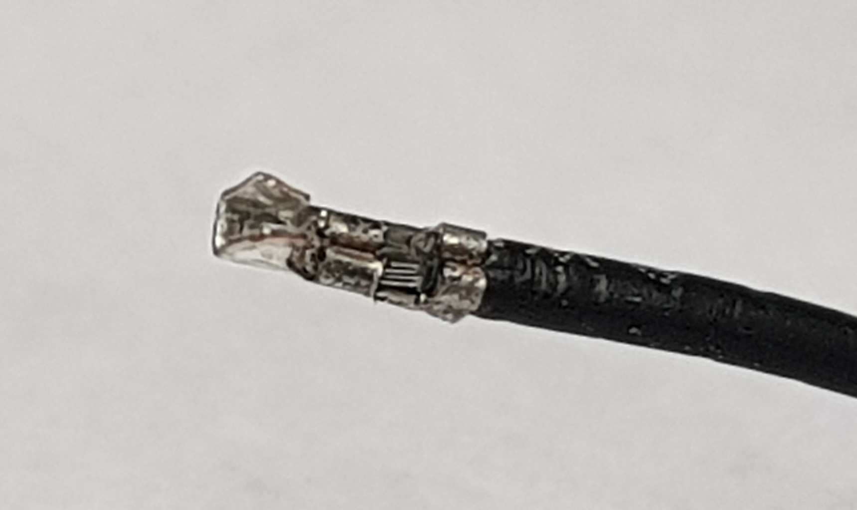
@ALXAndy is bang-on when he says how bad RGB/ARGB connectors are - always falling out or not lining up when you're trying to get them in. Aqua Computer actually uses some tiny JST style connectors on the Farbwerk (in addition to the standard type) and the RGBpx strips and I think I might standardise on those. As far as I can tell, they aren't JST though (as another post claimed) but Molex Picoblade. I've ordered some crimp pins and shells so we'll find out when those arrive. Incidentally, if you feel a dark tension in the atmosphere in a few days time, it's because those pins are 1.25mm pitch and tiny enough that there's going to be serious magnification required! ....and a LOT of colourful language! If I can do them - and I ought to be able to, they're not that different from the pins I had to crimp to externalise the Aquaero screen - it'll mean they stay put once plugged in.
Also on order are a couple of 90° molex power plugs which should let me power the Farbwerk and the Aquaero once mounted at the rear of the case...and still be able to shut the door!
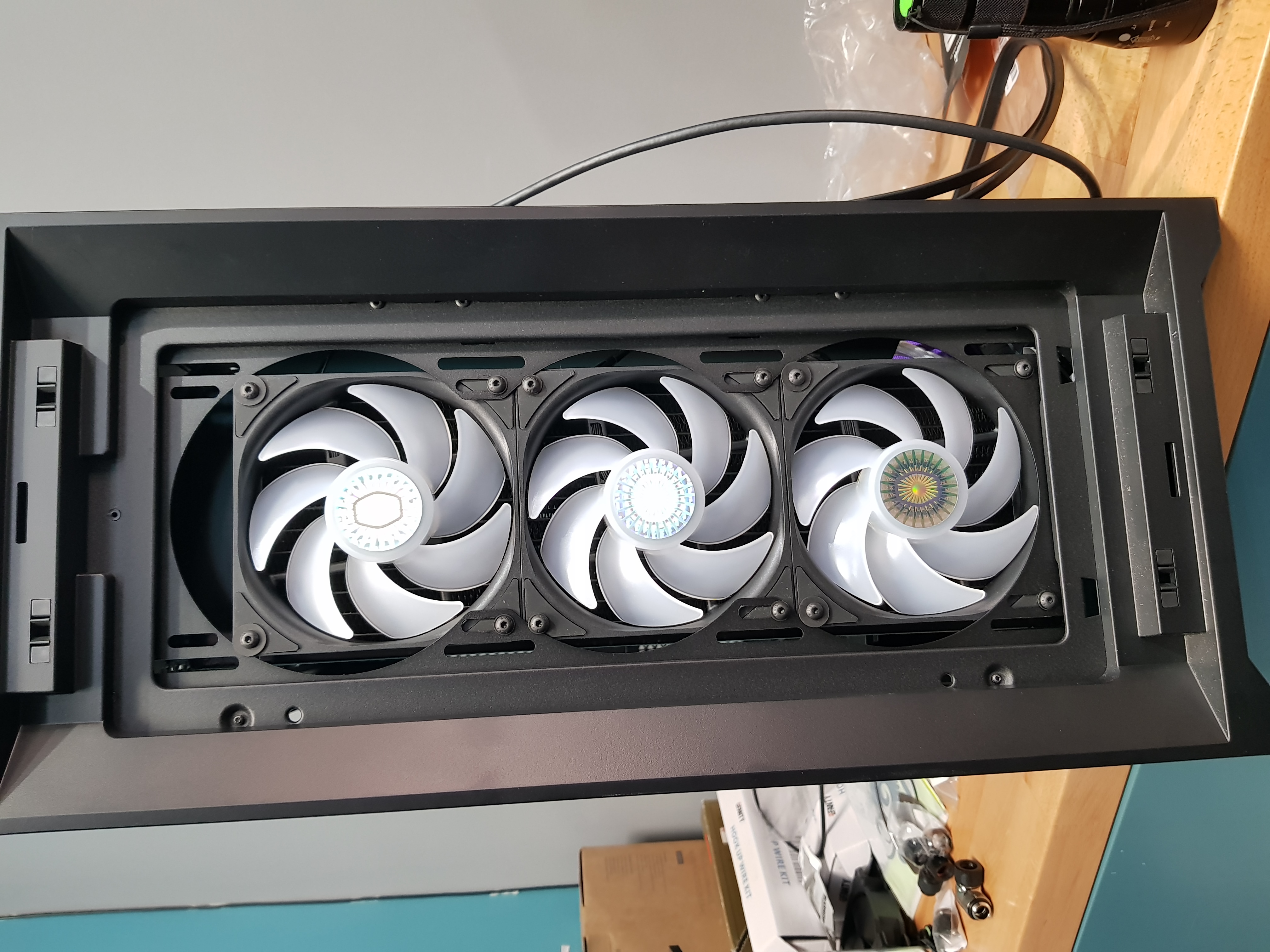
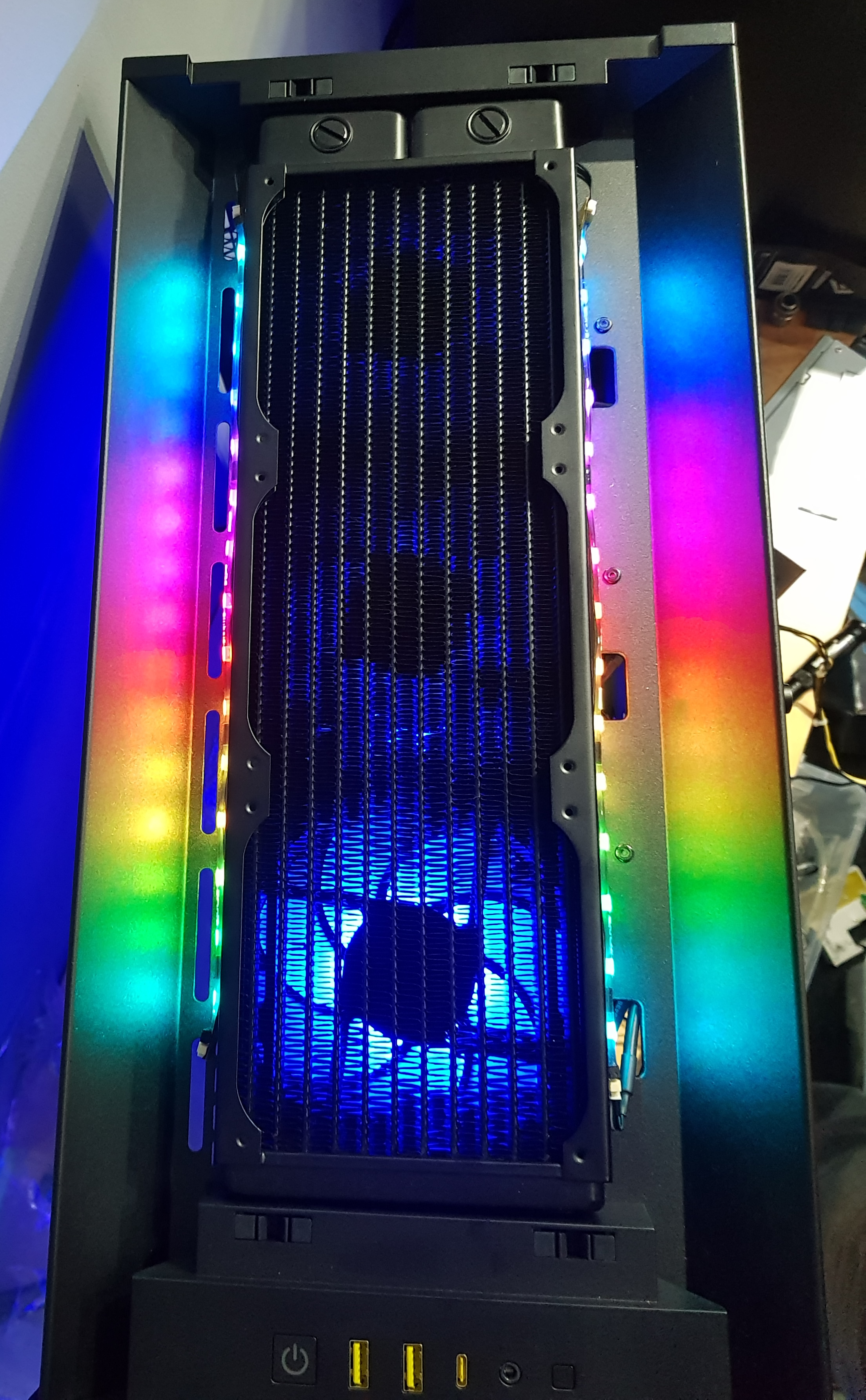
Also some coolant and some fans. I gave in. It's irritating but the only ones I have that are even a set of three at least similar fans are the silver ones that light up green when you power them. I was going to put up with them being silver as they're quite reasonable fans....but the green's going to clash with the purple something horrible!


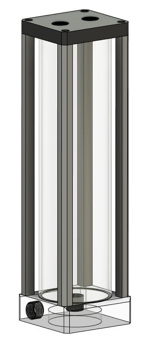
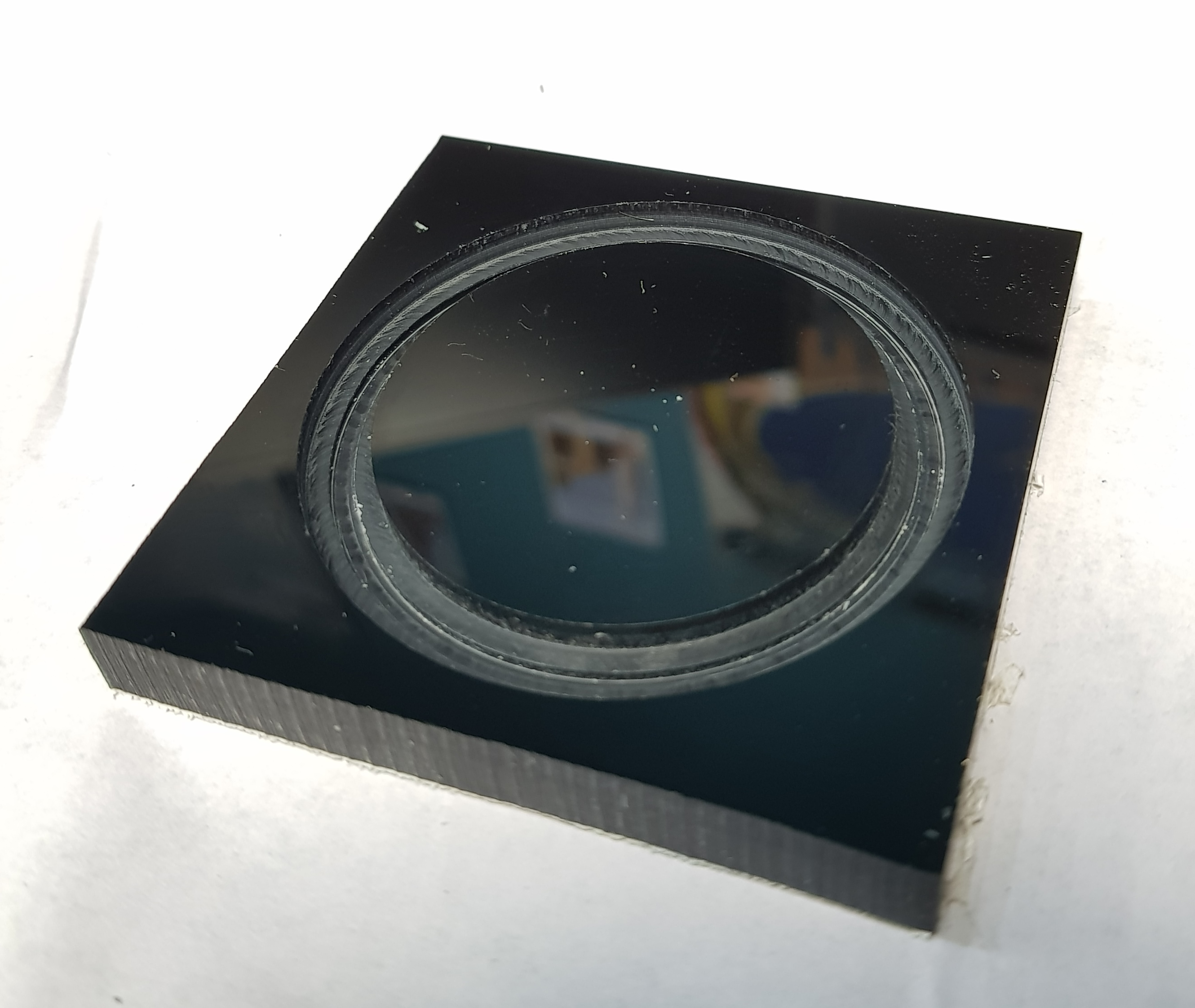
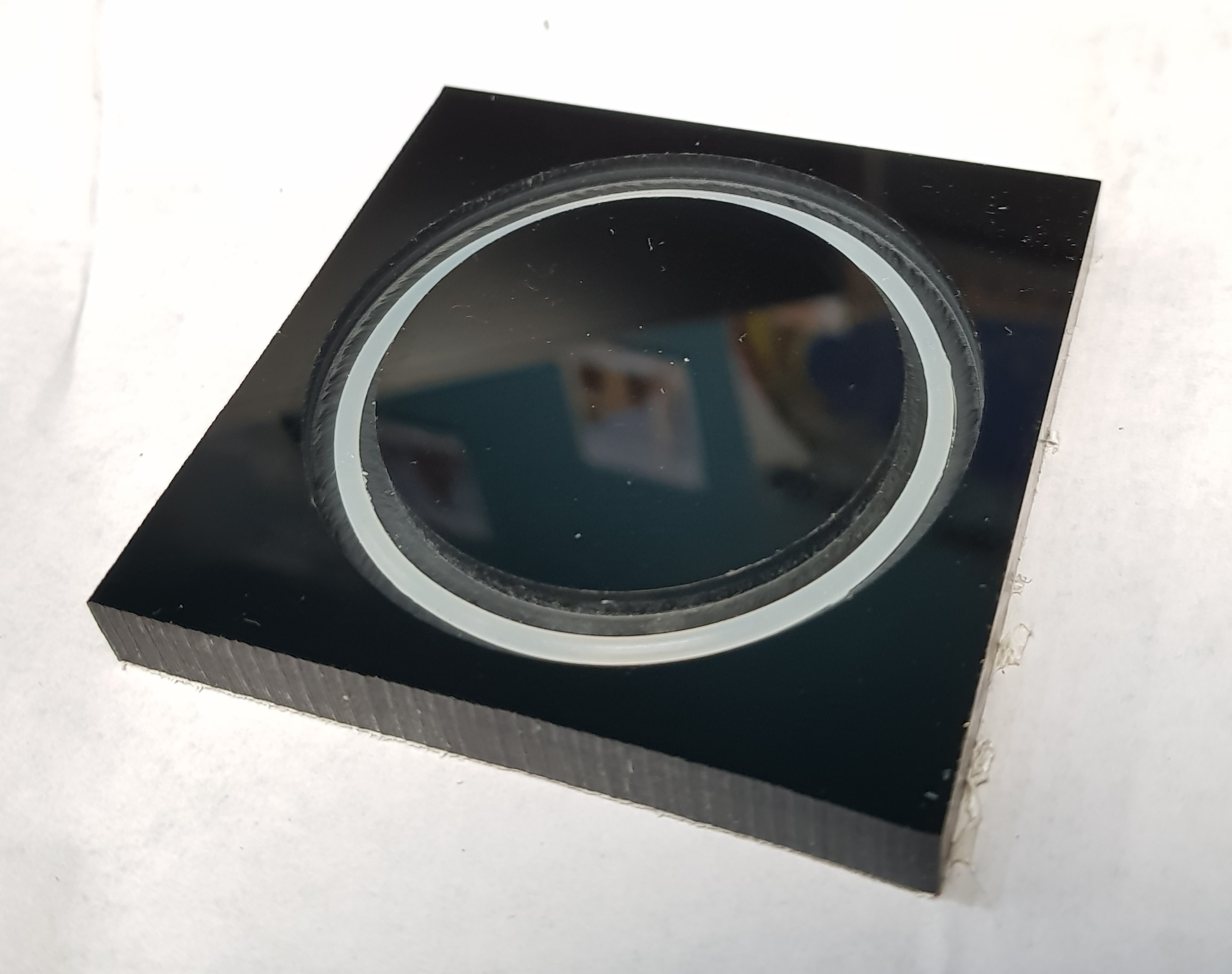
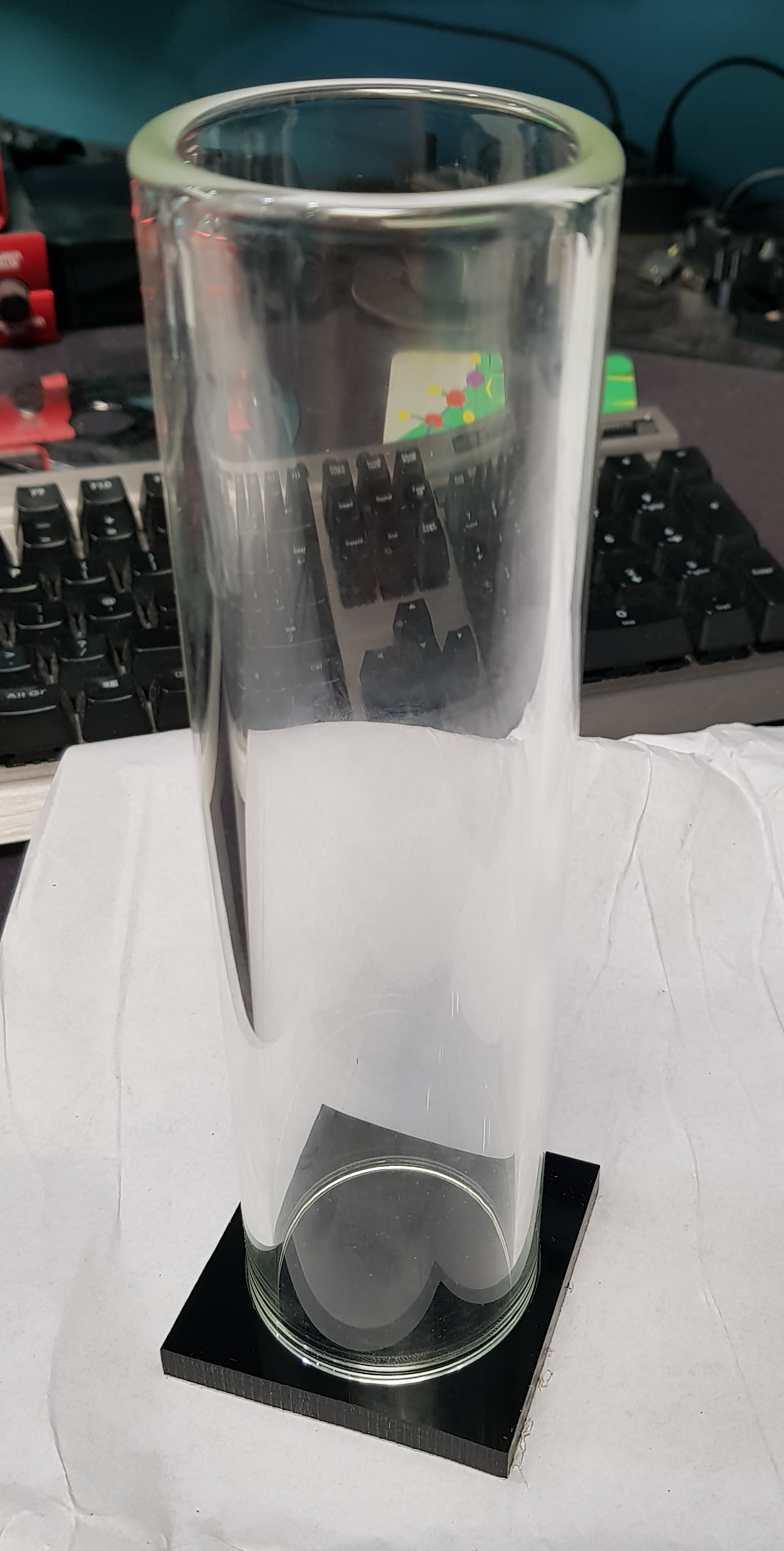
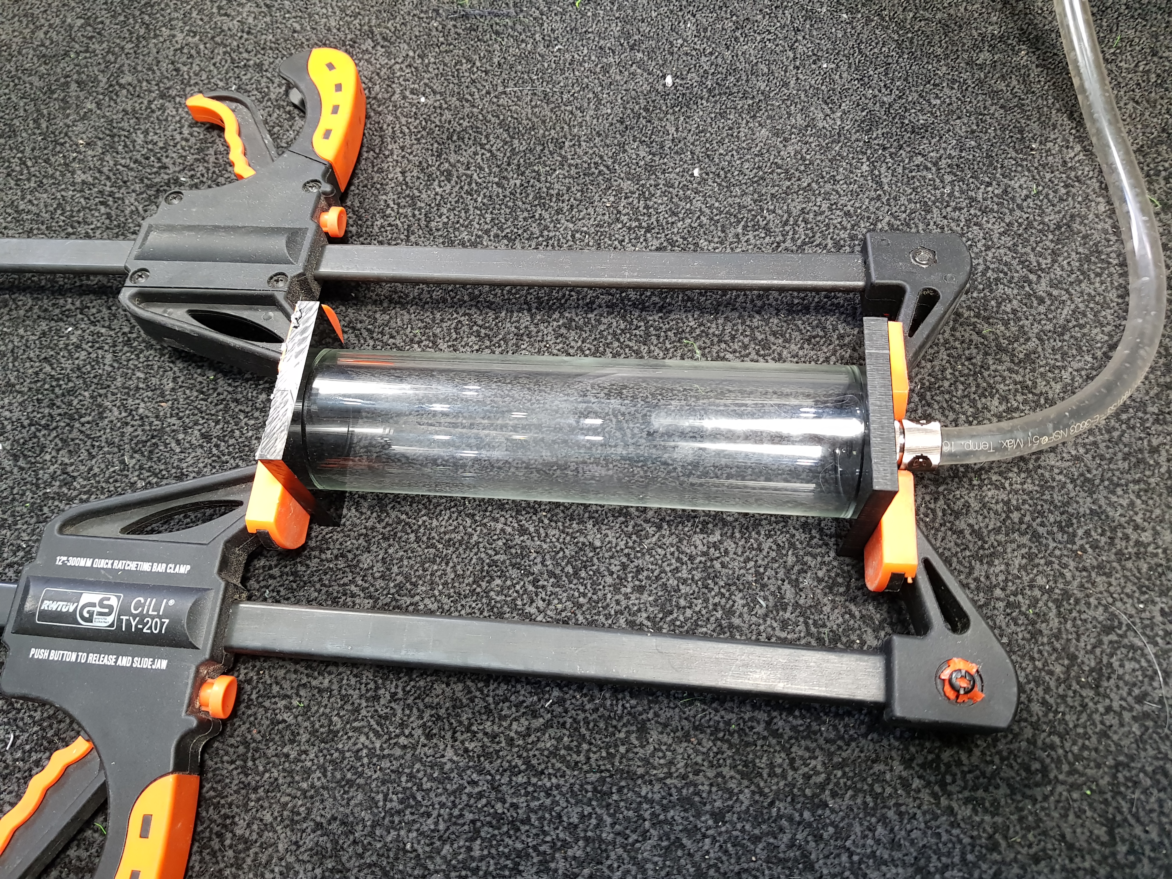
 I started idly surfing and browsing the reservoirs on offer and decided two things. It needs to be square rather than round and it needs to have the pump integrated into the bottom - both for aesthetics, you understand. I've built things with bits zip-tied together in the past and that's not what I want to do this time. The one I particularly like the look of was a Swiftech Maelstrom that has a (rounded) square tube but it's no longer available and has been replaced by a V2 that no longer has that. Also, like most others of this design, it takes a D5 pump...and that's not what I have. I also decided that I didn't want to throw a hundred-odd quid at the problem to make it go away