Project: Self-Inflicted

3D Printer has finished. In hindsight I probably should have designed an overlap between the two parts to block the light - too big to print as one long part - but the two seem to close up pretty well with a little trimming and aligning. You can see in the second pic how it's a lot less hot-spot'y now.


Found some 3M VHB (double-sided adhesive clear gum) to stick the ends of the strips down as they were starting to peel already. Hopefully that should keep them in place.
 
4mm wide LED strip just arrived to convert the RAM heatsinks from RGB to ARGB. Yay! How wide is a 4mm strip? That's right, 5.6mm! No way that's going to fit into the available space. Also it's made with 5050 LEDs (for those that aren't aware, that's 5mm x 5mm) instead of 3535 LEDs so it HAS to be the wrong item sent. Good job I've not waited over two weeks for them to arrive or I might be annoyed! *facepalm*
 
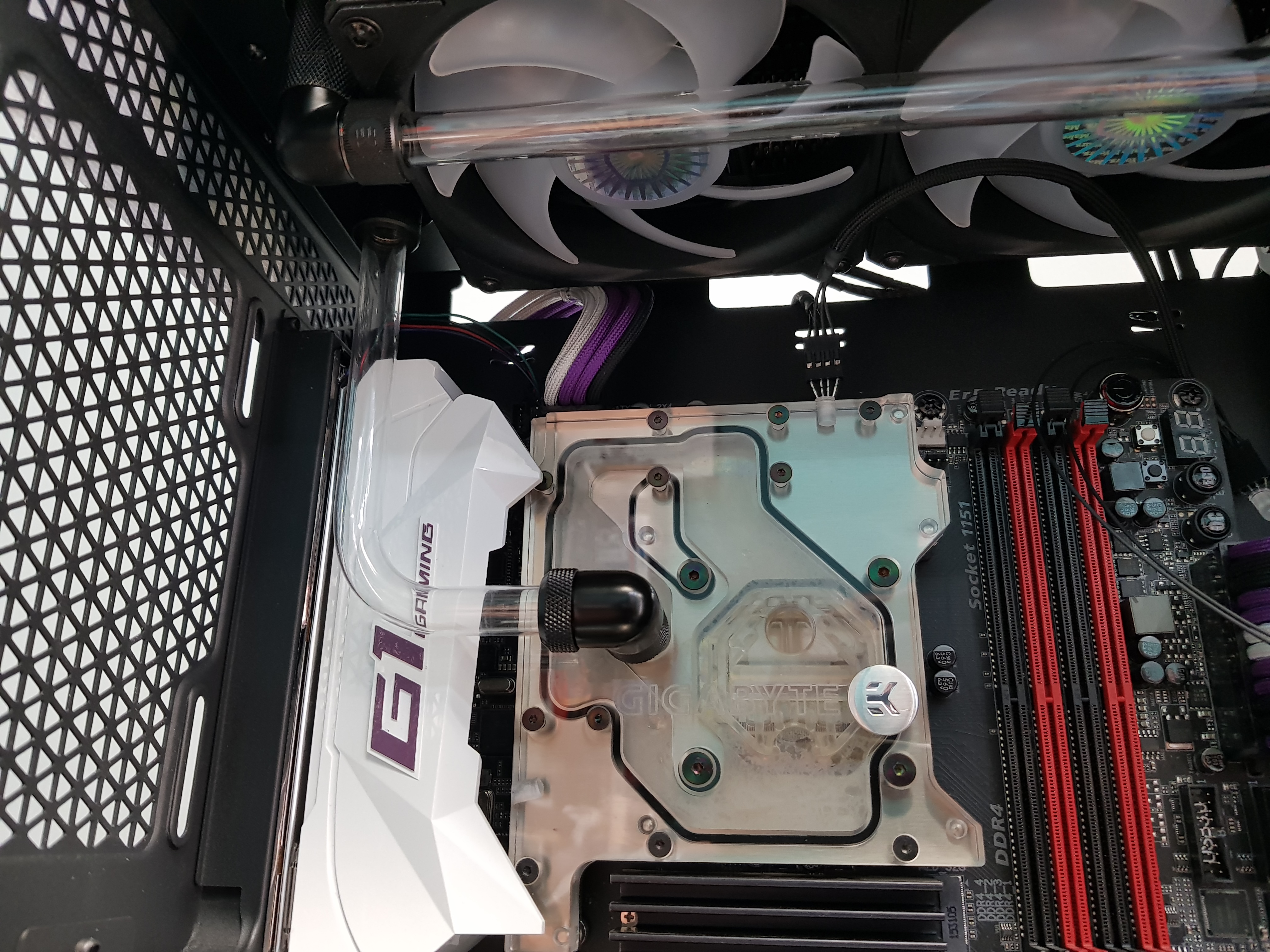
Ok, new toys arrived and this time in the correct size. So I'd like to ask for opinions please.

These are the RAM heatsinks. One of you is going to recognise them! They are the only RGB component in the system; the rest are all aRGB/DRGB/RGBpx - pick your preferred acronym. I want to make everything ARGB as it will simplify things to have one controller instead of two and potentially it'll look odd if the RAM can't match the rest. I don't want to replace the RAM with ready-made ARGB RAM for two reasons: 1. I'm a cheapskate :D and 2. It requires a different control software and I'd rather everything was on one controller. So I want to convert them.


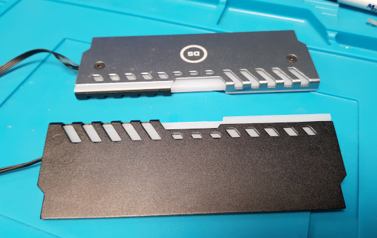
First question. Do I leave them half silver, half black or do I spray the silver side black?

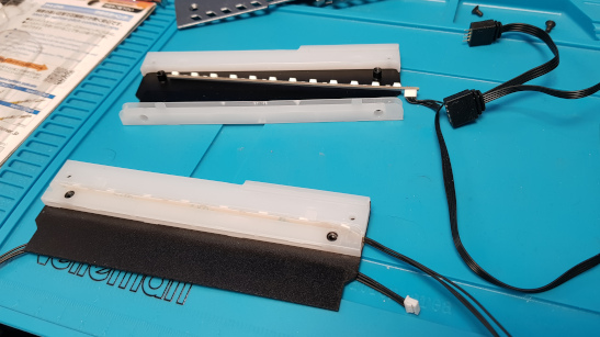
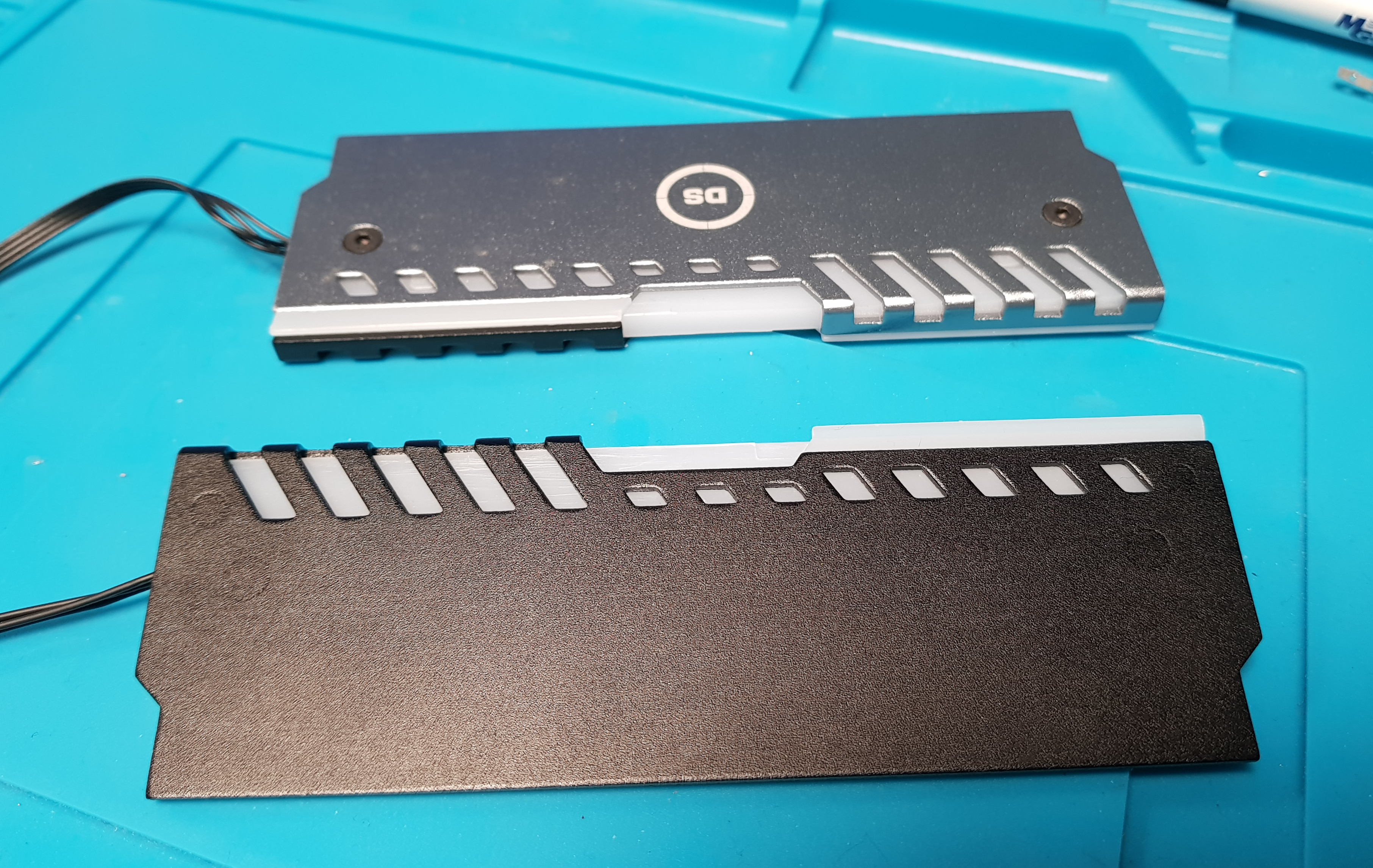
The internals look like this. RGB at the top and my prototype conversion at the bottom. I can seat the tape better once I'm happy with it but actually it doesn't degrade the effect you can see from the outside.
You can also see the loop-through RGB connectors on the old.


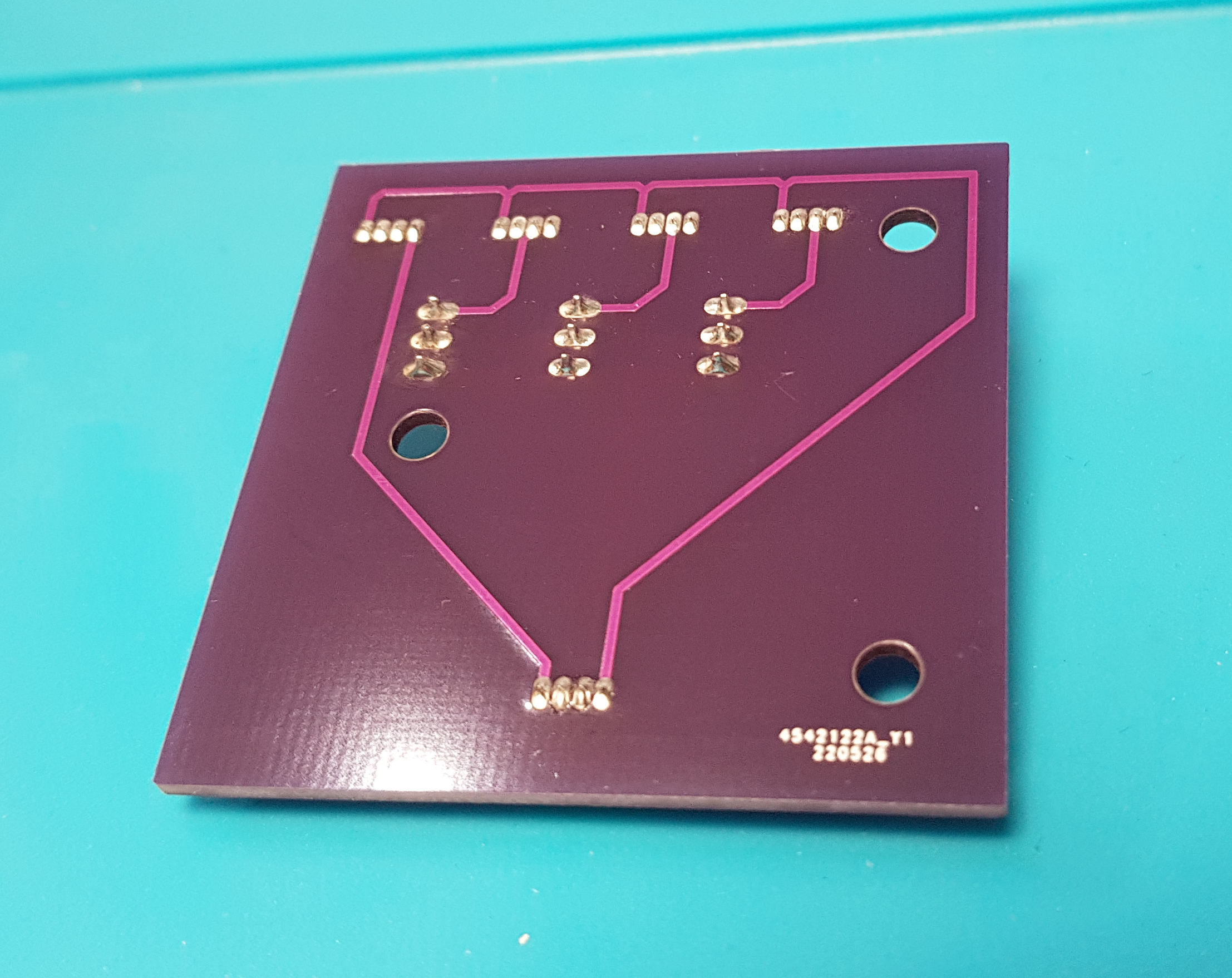
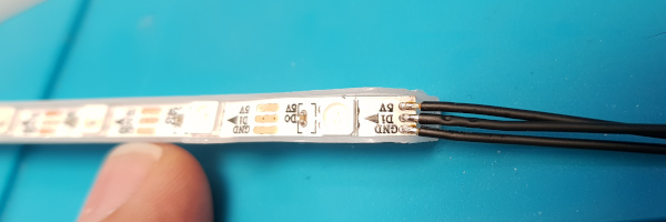
This is the (horribly over-exposed) strip and the connections to it.


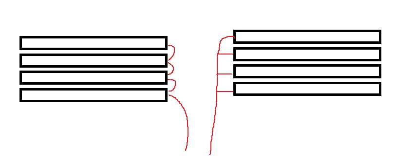
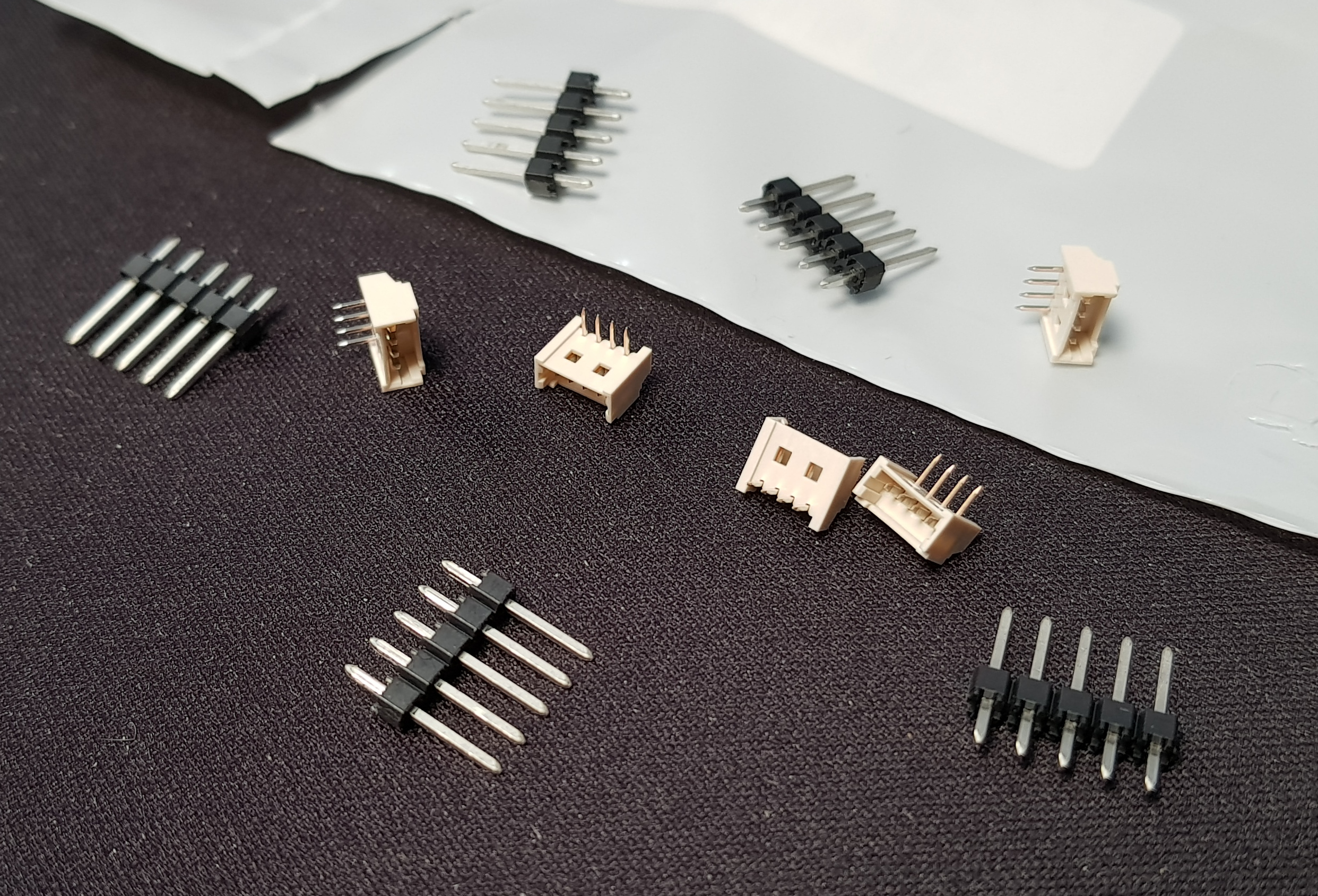
Next question then. Do I hardwire all four heatsinks together in a chain by soldering a shorter length of wire over the top piggy-back style and maybe backed up with some silicone or hot-glue as insulation or do I try to emulate the loop-through plugs setup that was there originally. My gut is to just solder them in a chain as I think that will be neater (easier to hide the wiring) and I can't really think of a good way of doing connectors that are a less hideous mess than the previous ones.....but I'm open to suggestions! I could also try to solder the wires in T connections externally rather than on the strip - more fiddly but may be necessary if the piggy-backing doesn't work well.

It's also worth noting that by piggy-backing the wiring, I'd not technically be chaining them together, they'd be split. The difference being that if we have 8 LEDs in each module, with them split they appear to the controller as 8 total LEDs so each stick will do the identical thing since each of them has LEDs numbered 1 to 8. I could run the data wire to the next module from the other end of the strip and that would result in a proper chain with the first module having LEDs numbered 1 to 8, the second having 9 to 17 and so on. There are pros and cons to this: it would allow each module to be different....but I'm not sure that's a good or necessary thing. The downside is that for a 'rotating rainbow' - which I suspect may be what ends up being used most - if you have 8 LEDs and that's it, you can make the rainbow 8 LEDs wide and you get one of each colour of the rainbow and they cycle. OR you can make the rainbow up to 90 LEDs (max for channel) wide and you get a section of the rainbow scrolling through...which tends to look better on straight strips. It works because the other 82 LEDs don't display as they don't exist. You can't do that if the next numbered LEDs do exist on another module - or you can but the effect you'd get would be that the rainbow cycled down one module and then down the next...if that makes sense.
 
It's going to be a four-dimm setup (4x4GB) so I have double the number of connections to test my sanity with! There's no way I can get more than one wire into a picoblade connection. I could probably do two into some other type of connection but definitely not four. The way I see it, the options are these...but with three wires where I've only drawn one. Excuse the mashed up pic :D

RAM-LEDs4.jpg


What do you think on the silver half too?
 
Hmmm, that's certainly some things to think about. I think I can come up with a half-decent excuse not to go to those lengths for the RAM :D Because of their angle and how closely packed together they are, there's only really one face you'd see at all so it's really more about the top edge of them. I think silver is definitely wrong - not painfully so but still wrong. I'd not thought about white rather than black....but I'm in two minds whether there's too much white already. That really gives me a choice of:

Black - Black
Black - White
Black - Purple

And if I go purple, I'd probably end up having to buy all four cans because you just know that whichever one you picked would be wrong! I'd be swaying towards the Kobra Melanzana (See Andy, I do listen!) or Montana Galaxy If I had to pick just one....which is definitely something appealing about just making it black! Also, I think if I painted them in purple, I'd just have to redo the purple that went on the board to match. Damn, how did I get here from wiring?! :confused::cry:

RAM-LEDs5.jpg


I don't hate the idea of four neat sleeved wires leaving the board vertically, wrapping over the top and into the void at the back which actually has its own door to cover your sins.....which, of course is why I'm making it look pretty :rolleyes: 
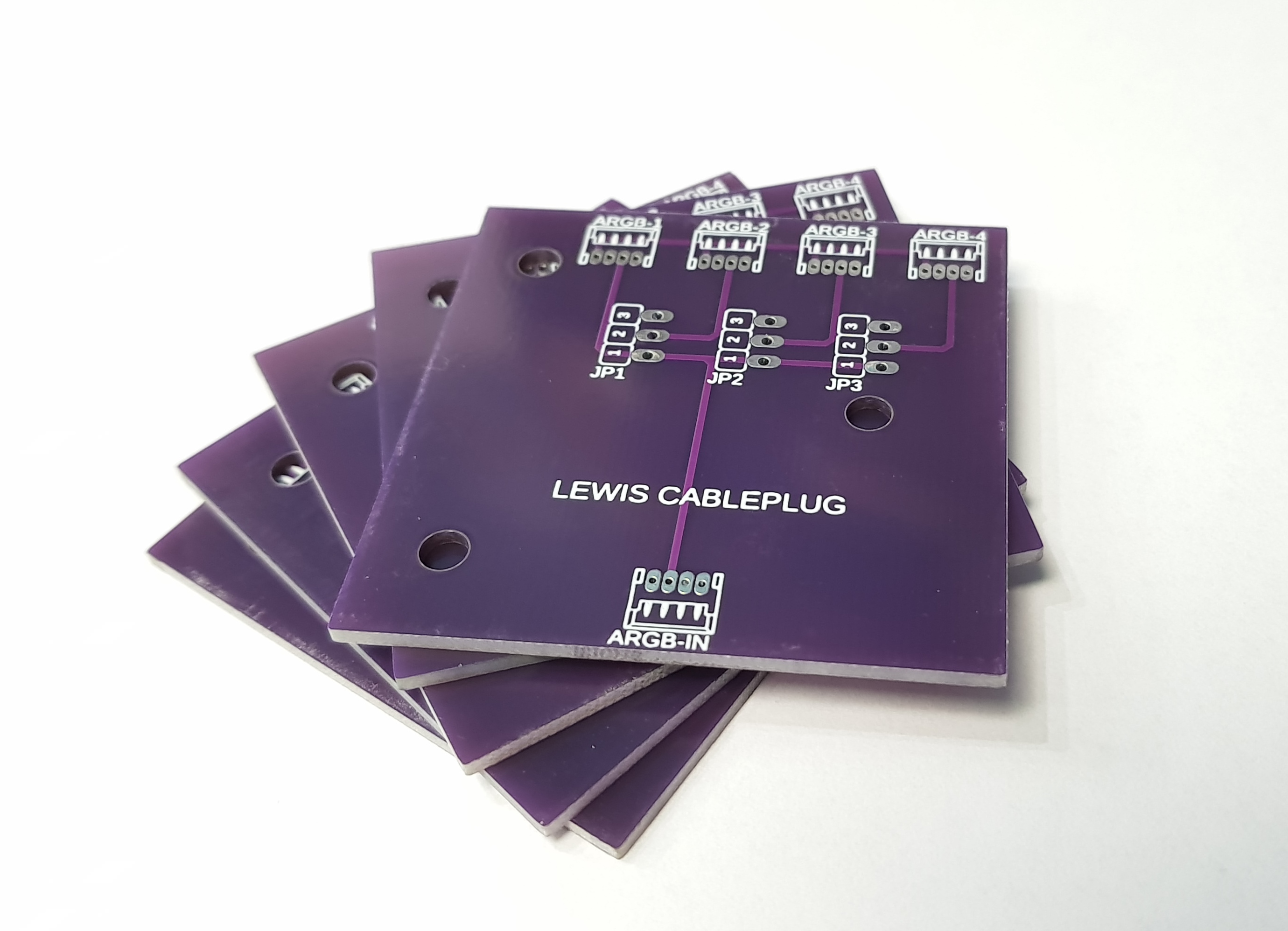
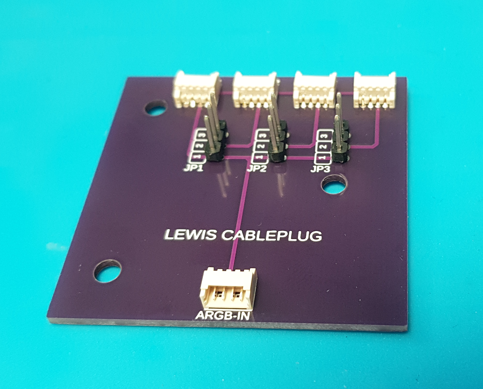
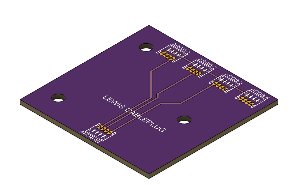
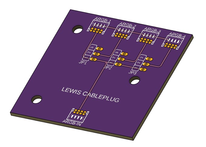
Individual, pluggable runs would definitely make it easier to make and manage. There was a mount on the back for a fan hub that I thought about pressing into service....but it's more complicated than it needs to be with separate power and a PWM repeater. The mount points could be co-opted though! If I go PCB, are there any prototype fabs you'd recommend/avoid?
 
Cool, I'll have a look. If you're going to the trouble, surely 'fancy' is the only way to go, no?!

In the meantime, I started wiring the CPU-GPU ARGB LED chain. Only the CPU pair so far as until I disable a PC, the GPU isn't there so I don't know the length of the wire...hence the trailing pair left.


These are 5mm dome type WS2812b addressable RGB LEDs run directly from a Farbwerk 360. It may not be necessary to make the actual LEDs pluggable but I did it for my non-addressable RGB LEDs when I replaced them as an easy way of replacing them if they fail again. This way I guarantee they won't ever fail :p

Edit: Obviously when fitted properly the LEDs will be bent at 90° so the connector lies flat against the block and the wiring will be routed under the cowl at the back so it's out of sight....just no point doing any of that until the chain is complete.
 
Well obviously, I blame @LePhuronn entirely for this :p but it looks PCB is going to be the route we go. Necessary? Perhaps not but it's something I've thought about doing a few times previously and never gone ahead with. At something like a fiver for the board and shipping plus something like £2.40 for the connectors (same Molex Picoblade seemed a wise choice) it's time to change that!

I've been watching some YouTube videos on how to do it in Fusion 360. It's not actually that hard once you wrap your head around the way they want you to do it...but deciphering that on your own would be a miracle!
This is what I've come up with so far:

RAM-RGB-PCB1.jpg


Now all I'm umming and ahhing about is whether to do a version with a jumper(s) that lets you select between splitting the signal and properly daisy chaining it!

Can't make life too easy for myself now can I!?
 
It's not similar to Eagle....it IS Eagle. They bought the company and have been rolling the two together. I suspect that's why the workflow is really convoluted - at least from my starting point. You have to start an Electronics Design - which appears to be a document but acts more like a project. Then design a schematic for it. Convert that to a 2D PCB and lay out the components and tracks. Then push that to a 3D PCB.
To complicate things, you can optionally start with making a 3D PCB from a sketch in a model - like you might want to do if you want the board to fit an existing enclosure or mount points etc. That 3D PCB then gets linked into that chain. It's a bit of a knot but it's walked through in the video that's part of a series I was conveniently already watching.
This is the video you want to watch: https://youtu.be/RRJMilcWBIQ?t=158

The only gotcha I've hit so far has been that for some reason the connector seems to flip between the schematic and the PCB; so pin 1 starts on the right and ends up on the left so suddenly you've got your data line and your N/C pin reversed and it wouldn't have worked. I just mirrored (tick-box) the connector in the schematic and all was well....but lucky I spotted it! Don't know why but it'll either be my inexperience of the product/field or just that one connector definition.
 
Meant to say :rolleyes: Was looking at JLCPCB just because they have the option for cheaper shipping at £3.10 for 2-week shipping.
Probably similar to you, I'm not sure I like the auto route of traces. Not because it's bad/wrong but because it looks nothing like what I had in my head. What I had in my head was much simpler and tidier so I did it manually. If you're talking a bunch of components with lots of pins etc, I don't doubt it's a good way to go.
 
Right, I did a version that was hardwired to do a proper daisy chain of the LEDs in the DIMMS. It should be possible to take a wire from the data pin at the far end of the strip and bring that out as a data out. I didn't want to commit to definitely being able to do that - as I've not tried it yet - so I then did this version that is jumper-switchable from split to chain....and I feel very smug about it :D Order's in, now to get the connectors ordered to solder onto the thing!

RAM-RGB-PCB2.jpg
 
Mounting location all sorted! The case came with a fan hub thing that's mounted on three standoffs at the rear of the case. I was thinking of trying to press that into service but between the SATA power and the PWM repeater, it was more hassle that it was worth....but the mounting points are up for grabs! Hence the three holes in the board. The rear of the case has a hinged door covering the cable area that I've (obviously) spent time making look pretty. Once closed, you can't see any of it...and if you could, there's then a solid case panel that goes over the lot. So yeah, the purple colour is going to be entirely unappreciated...but it was an option...and it was free...so I have five! :D
The switches are just going to be plain old jumpers. Actually, I need to see if I can find as many as three of the things! Should be screwed down tight enough that I can pull them off quite easily...but it's not intended to be changed all that often. Nice to have the choice for an extra 86p. No change in board price but I needed the pin headers (jumper pins) to solder into the headers. Probably got some lurking around somewhere but they'll only come to light if I've already bought some replacements.

Incidentally, there's traces on the back for power - couldn't put all of it on the front as there's too much cross-over of pins and I didn't want to make the pinout non-standard to avoid that and instead cause other problems for myself when I forget that it's not the same on the outputs as it is for the input!
 
Cheers.

Went and collected the components that will need soldering to the board. The pin headers for the jumpers are 5-way but I can cut them down to 3-way. It's just what was available in a pack of 5 rather than a pack 20,000!
The pins on the beige parts measure 0.32mm and are 1mm apart....so wish me luck when it comes to soldering those!

 
Tiny update. Had a quick go at bending the CPU to rad tube since it was possible to do that in isolation. I give you.....an unimpressive looking bit of tube :D
Also the rad to rad run that I've no shortened once I realised the fans were mounted the wrong side of the rad :rolleyes:


Obviously, because I've done this before (a number of years back now), I had no problem getting this done perfectly, first time off the bat....so there aren't any pictures of (in order of appearance):
  • Too cold - creased on bending
  • Too hot - bubbles at bend
  • perfect temperature.....but not realising that it hadn't gone a full 90 on my butchered mandrel


I've also just received the extra 4mm wide ARGB strip for making up the RAM blocks....so I'll try to get my finger out on that :D
 
These arrived this morning :D A carbon copy of the CAD design. Like 3D printing...only better quality :D


Have to go do some actual work but I have a feeling there may be some soldering in the near future!
 
Surprisingly stress-free! Touch of trouble getting the first pin header straight. It would have worked....but you can't have it crooked! The tiny picoblade headers were easier as they have a larger base so they sat flat more easily...and were near enough to the edge that I could clamp them with a helping hand.


Now all I need to do is find some jumpers to go on them! *facepalm*
 
Ahhh the joys of hindsight! You see the top two mounting holes? Where the track goes rather close to them? Yeah, that's where the stand-offs will sit against. Now there's maybe enough room it doesn't touch and there is solder mask over the top so it might not cut through it and short it out....but I don't like "maybe" and "might"! A couple of plastic washers between the standoffs and the board will sort it....but it's annoyingly short-sighted!
 
It does seem of late that you buy a tool only to have to finish/adjust/perfect it yourself. That or you pay an arm and a leg for it....and then it's 50-50 at best!
Yeah, the PCB issue is certainly fixable...I'm just annoyed that I failed to engage brain enough to realise there would need to be clearance for the screw head and the standoff. For the next one maybe I'll have learned!
In the meantime, I've found enough nylon washers of a near enough size to fit - thought I was going to have to machine my own for a bit...which is just nuts. Haven't got any spare jumpers so have ordered a pack. For the moment I found two of the three jumpers I need on some Splittys (which will need them back) and I've made one from dupont crimps just so I can get it tested. Can't test it quite yet as I share a home office with my wife and the beep of the continuity tester wouldn't go down well on her video conferences :rolleyes: Sooon though :D
 
I don't mind fettling a tool if I've knowingly bought it for a song with the understanding that it: won't be deburred in any way, will need some adjustment (possibly with a fourteen-pound lump hammer - bonus points for getting the reference!) and will be liberally coated in some old engine oil that's been round the factory manager's car for a good few thousand miles. I get upset if I buy a well-respected brand for an heirloom price and then find that they've outsourced it to China and it's all of the above but with some of the oil wiped off and in a nice red box. :mad:

A rather insipid-looking picture (I think the camera was having trouble with the white balance as it's not like that in the 'flesh') of progress so far:


Continuity testing done, jumper fabricobbled, mounted and new sleeved cable of insanely small crimps made up. Realised that I'm going to need more of the crimps (and shells) as I'm now going to need one for each DIMM. I should probably get on and finish the RAM sink wires to length...but I'm going to need the crimps, half of the sink shells are drying and will need another coat of paint...and I've just taken delivery of and planted three trees. Yeah, it's been an odd day at work in IT! So I'm knackered and going to crack open a cold beer! :D
 
Back
Top Bottom