Project: Self-Inflicted

Ok now we're getting somewhere....not far mind! :D

Smurf poo applied - not enough to a complete strip but there aren't any chips in that middle bit so it should be fine.


Buttoned up, sleeved and crimped


These are just the default "Rotating rainbow" but depending on the jumper setting of the PCB, they all go in sync like this:


Or in series like this:


Could also use that to make each one a different colour or whatever as necessary. Could even replicate the colour striping of the wiring...although obviously without the black!
 
@LePhuronn Just don't make it too good...really can't be bothered to do it again! (I hate redoing things with a passion)

@Monkey Puzzle Yes. You can change colour/pattern/speed/brightness etc from Aquasuite. Even set individual LEDs to various colours depending on things like temperature or (I believe) events. Also runs (and would react to hardware temperature sensors) without software involvement.
 
Farbwerk 360 for the ARGB and there will be an Aquaero added for fans later but its a case of removing it from the donor PC as late as possible so that PC remains useable for as long as possible. Ditto with the GPU.
The Aquaero is, if I remember correctly, a 6XT but I think the plan will be to de-screen it and mount it in the rear next to the Farbwerk yiu cab see in post 106 above. Might seem a bit heathen but to be honest the screen is very rarely used - even initial setup is easier by plugging it into a laptop.
 
So, four months or so down the line and no progress. Given up? Nope, just "side-tracked". To cut a long story short (-ish!) it turns out that if you have a new downstairs toilet fitted, it doesn't work very well for very long if they connect it to a (shared) soakaway instead of an actual sewer. More fun when it rains and your new toilet has become the lowest opening *facepalm* So much fun ensued, some colourful language, almost literal throwing money down a hole and on top of that my workshop (small though it is) was the route between the BIG hole and the skip. So everything had to be packed up and has only just come out of storage.
Just for comedy, this is how you temporarily 'fix' the problem when you're told "Yeah, good luck with that!"


Right, and back to the point. Having previously made some proof of concept bits out of scrap acrylic, I got in some Delrin that was thick enough to take back-to-back fittings (inlet and anti-splash cone) and cut a 6mm circle into the bottom for the glass and a 2mm circle into the bottom of that for the o-ring:


Same was done to the top of the pump and I was forced to have a little lighting test. I'm hoping that it might illuminate the res more once it's filled but I'll need to wait until it's actually water-tight before I test that :D


I've started making the struts to compress the whole thing together. The astute of you (or those who still have enough fingers left to count up to four!) will notice what's wrong. I bought enough aluminium square bar to make four....but when the plan was for a wider, shorter glass tube. Now it's longer, I don't have enough...so that's in the post.


Why the numbers? Well each one is hand-fitted to the hole top and bottom so they're unique. I'll polish off the numbers when I'm done and have tested it. Shouldn't they all be identical? Well, yes but one of the top holes is off by about half a mm and one of the bottom holes has wandered by something similar. Not a lot but enough to make them all slightly different. Who needs simple anyway?! :rolleyes:
There's a bit of a gap showing at the top but once I have the last strut done, I can tighten them down and squish the o-rings. Worst case if there's still too much of a gap, I can shim it but there glass isn't perfectly square so some slack for adjustment is necessary unless I start lapping the ends of the glass....and I don't want to unless I'm absolutely forced to!

So at least there's some progress for you. One more strut and we get to see if it leaks horribly! :D
 
Also, cast your votes (we can pretend this is entirely democratic! :p ) for whether the struts should stay silver (bare aluminium) or be badly sprayed black. I'm torn to be honest.
 
You're the second that said polish then...and fir the same reason. That's good enough recommendation for me! :D

Well the Delrin came in a range of sizes with one of them being about perfect size for the part. You know that if you have just enough to do only one that you're BOUND to fubar it in some fashion....so I took the cheap insurance for that and bought a sheet U could get three of 'em out of. Just in case!
It's 10mm (nominal) thick so there is in theory, enough space for two fittings down one hole. I skimmed both sides on a lathe as the surface is as-extruded - not bad but not flat. Had to check, and it's 10.60mm +0/-0.04
If that's any good, drop me a sketch by email and I'll see what I can do.
 
Aluminium turned up and I made the last strut. Bolted it all together and pressure tested it. It passed! Even pressure tight moving it about and flexing it a bit. So obviously I had to mess with that! :rolleyes: The one thing that bugged me is that because the end of the glass tube wasn't square, it meant the top of the res was on the **** and the gaps between the lid and the struts was both variable and that there was a gap. So since the tubes came in twos, I thought I'd work on the other and lap it flat and square:


The theory was that at least I wasn't breaking a known-good if it went awry. Tried the 100 micron 3M microfinishing film I'd got stuck to some worktop offcut but it wasn't getting through it quick enough. Part of that I suspect is because I'd already partially worn it out on some chisels that were giving me grief. Anyway, the Extra-Extra Course diamond stone (told you those chisels were giving me grief!) is roughly equivilent to 120 grit and that took no prisoners! The white stuff you can see in the picture is glass slurry - keep it wet and the stuff doesn't get airbourne and attack your lungs. Some of the other film was then used to smooth out the result to get a better seal.
Now the top goes on nice and flat and the pressure test....fails :rolleyes: Told you I'd messed with it! I think though the problem is simply that the tube is shorter so there's not enough squish on the o-rings. Loosening it all off there's only about 0.5mm of squish when they're fully tightened down so I need to take maybe 0.5mm off each of the struts to get it pressure tight again.


...and then I have to mirror polish them to boot. Why did I ask for suggestions on how to make my life more difficult?! :p
 
Ok, so I've succeeded in making a mess!


The chunk of wood you can see is where I quite quickly made a jig to hold the bar while I lapped the sides. My fingers hacked one bar but there were three left to go! The slots to the side are to pry the bar back out again - no prizes for guessing whether this was an afterthought! :D
That's 320 grit using WD40 to wet it - which helped stop it clogging up quite so much. Should have then gone to 600 grit but thought I'd get away with it after a much smaller test piece.

I tried blue compound but ended up finding the brown to be more effective - certainly faster and that was really much criteria :D Then I gave it a final buff with some pink. All on separate wheels so as not to mix the compounds. The wheels are mounted on an arbour in my lathe....which now needs a good clean too :rolleyes:


Howzat?! Well, to be perfectly honest with you, it's not quite as good as the potato pics make it out to be. You can see some scratches where I really should have taken it to 600 before polishing....but it's pretty good for a first go, I've learned some and I don't think it'll notice once mounted to be honest so it's not worth starting from scratch.


Fully assembled and ready for pressure test - which I did before this pic was taken, so before swapping out the blanking plugs for the pressure relief membrane etc.....in case you were wondering :D


Initial pic on the left and 16 hours later on the right. That's what, half a psi over 16 hours? I'll take that! Also, well within the realms for temperature variation too - the first test before I lapped the glass actually rose in pressure.


Right, now I just need to start punching holes in the case for some pass-throughs....couldn't make the pipework easy for myself now, could I!? :D
 
Hmmm, it might be good to be certain of exactly where said hole needs to be before I go making fairly irreversible changes :D I intend the res to be 'mounted' in the pipework rather than screwed to anything. So there will be an input at the top that it will hang from and an output from the bottom that will connect to a pass-through to the rear of the case, down, under the shroud for a hidden drain tap and back up through the shroud with another pass-through. I also want to use Barrow D-Plugs for the connections to the res so that there is some form of vibration isolation in the form of o-rings. Might be unnecessary or ineffective but that's the plan. So the top pipework will be largely solid and cannot have any rotaries in some planes or it'll just flop. Started doing that and have it roughly figured out but need to wait for some more parts before I commit. Found that it'd be useful to have the plastic front part of the shroud fitted as somewhere to put the res down while I'm working on it. Already knew that it needed a notch to clear the rad. It's only 38mm thick, that's not unexpectedly chunky, right? It does seem they only allowed for really thin rads in this case.

So this is the plastic shroud extension fitted. There is another version supplied that curves downward but I want the air to be able to flow out the bottom fan and out through the PSU. You can see the notch cut in the front right of it.


That cut, it still didn't fit. Found the leg at the back (when looking from the open side of the case) hit the rad. I marked it out in white but there wasn't enough depth of plastic there that could just cut or file some clearance. Well, if at first you don't succeed....CHEAT! :D Gas-fired soldering iron with a hot-air attachment as my tool of choice and now it fits :D It's a little over-cooked in a couple of spots - which meant I discovered that I could have done with better ventilation *cough* - but it won't be seen anyway.


Part out of the case so it's a bit clearer - quite difficult to get a good picture of it in-situ. Harder still to heat it to softening and bend it in-situ; which I needed to do for the last bit in order to get the foot to line up with the existing screw hole. The trick, of course, is to not cook anything else in the area :D


Back to waiting for the post now....good job they aren't striking every few days! :rolleyes:
 
New fittings arrived to see if I can make a chain of non-rotatable fittings that end up pointing in the right direction. Some how I have straight extensions and right-angle bends that don't screw together...from the same manufacturer. Odd right? Well it get's odder as the bends will screw into other fittings just fine and other fittings will screw into the extensions just fine....the only thing that won't is that combination, that way round - the extension will screw into the bend...because that's not the way round that I need it! No point in sending them back as I'd just get more the same. Fortunately, resistance is futile...it just results in a light dusting of paint and brass flakes


And now we have a chain of fittings that I should be able to hang the res off. Apologies for the (extra) poor pic; the choice was top in focus, bottom in focus or the whole thing too far away.


So the top bit screws into the rad - you're getting a rad's eye view so to speak. The bottom fitting will go through the midplate via a pass-through. That fitting (and the one screwed into the res top that's too blurred to make out) is a Barrow D-Plug. They make them in three different lengths but the longer 25mm one gives me room to add an extra o-ring so that there's no metal to metal contact...so in theory it will absorb or at least lessen any transmission of pump vibrations. They're stiff enough (if that's the right term) that it won't pull out with the weight of the empty res hanging off it. The extra support from the one at the bottom ought to handle the extra weight of the coolant. A sensible man might have considered putting the disconnect in the horizontal part of the chain.....but he was away when the planing was done :D

 
Last edited:
Ok, time to make irreversible changes by drilling big holes in things :eek: Centre punch, step drill (normal drills tend to make triangular holes in thin metal) to 10mm and then a Q-punch (thing with a bolt through it at the bottom) to take it up to 20.4mm for the 20mm pass-through fitting. Then a spot of deburring to get rid of the sharp edges.
The vertical post-it was just for layout marking. The horizontal ones were just to protect the surface. You can tell when someone needs a good roll of masking tape when...!
On to the duct tape next. That's there because you should ALWAYS strip all electronic components and wiring out of the case before making lots of tiny conductive metal chips inside your case.....but I couldn't be bothered. Duct tape dams back and front with the sticky side towards the hole to catch the swarf and then a good clean-up afterwards.


And one floating res with very little apparent suport. I would say that the top fittings won't be visible, being black on black....but once DISCO mode is enabled, all bets are off!


The screws in the pump heatsink are there just to blank off the mounting holes....they looked ugly! :D Oh, and I painted them black because they weren't black enough :D

Now I'm just trying to sort out the return pass-through that will feed the GPU. It'll be coming up in that solid bit of the PSU shroud and then S-bending over to the GPU. I could really do with a 60° fitting to make it work. 60° you say? Yes, they're unusual...but I have one....I've got pictorial evidence that I bought two of them for my last project (and only used one of them) too! Can I find it? Can I *&%^! I've got two 30° fittings which I can use but it's still annoying me. Yes, those are unusual too; they're rather old Koolance fittings. I expect the 60 will show up shortly after the loop is first filled!
 
Time for a progress update with some particularly potatoey pictures! :D

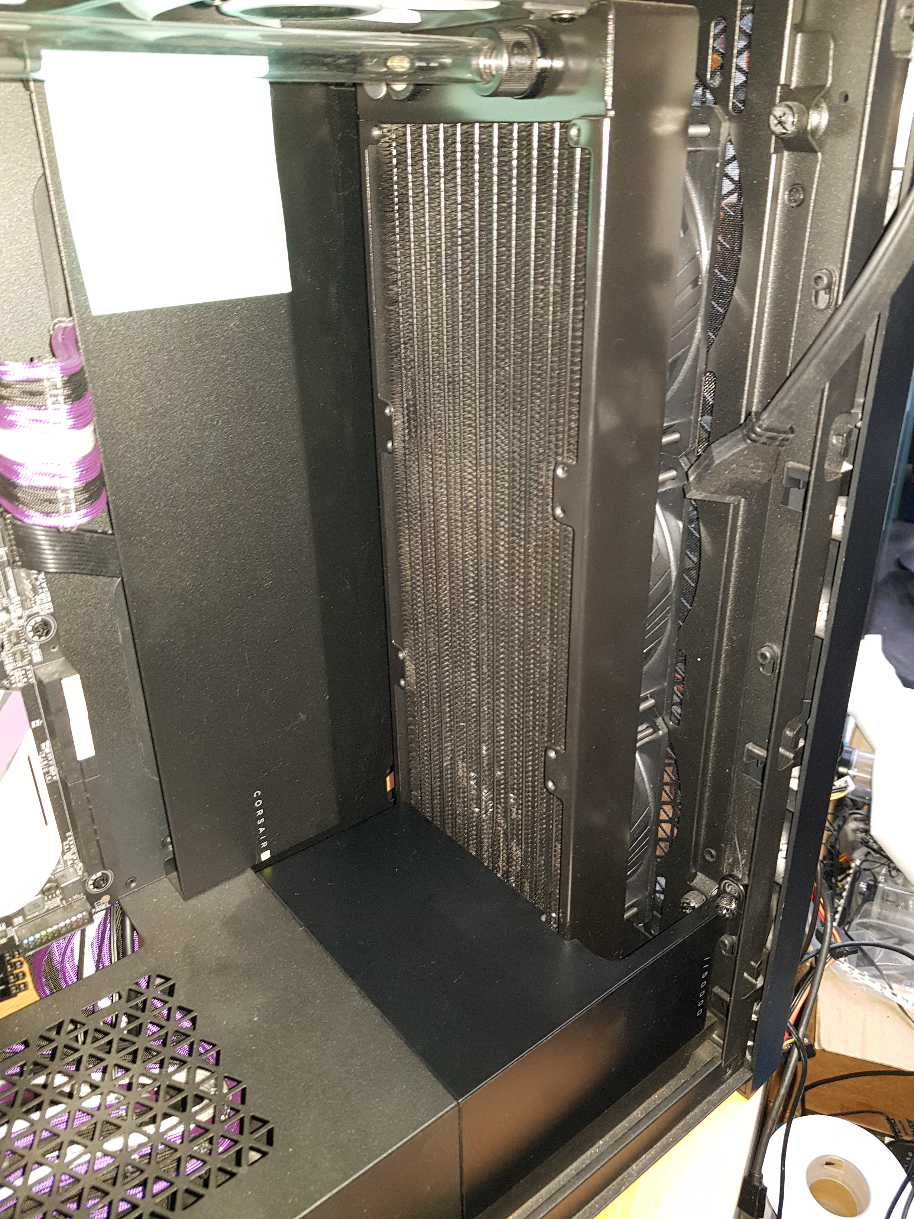
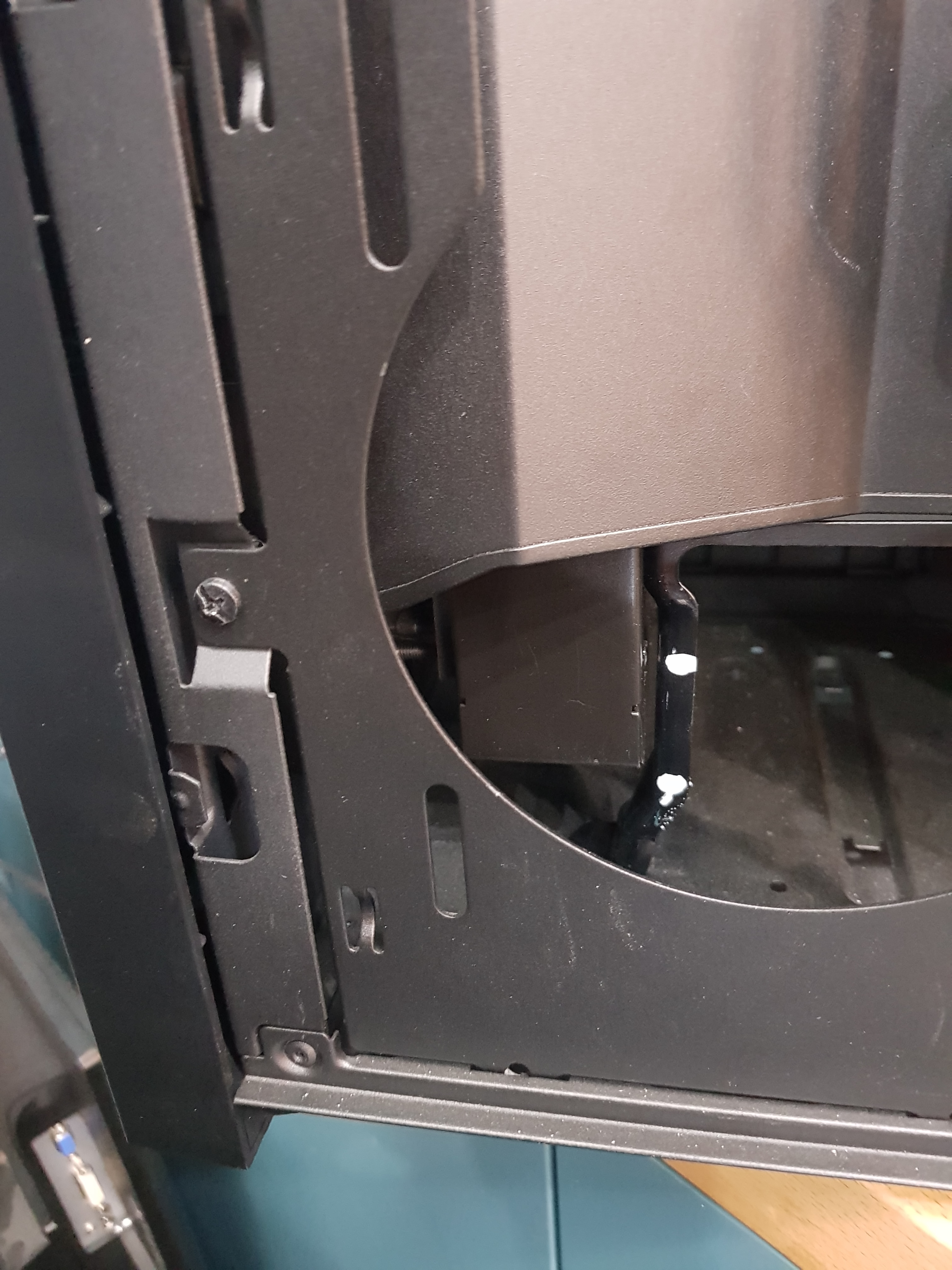
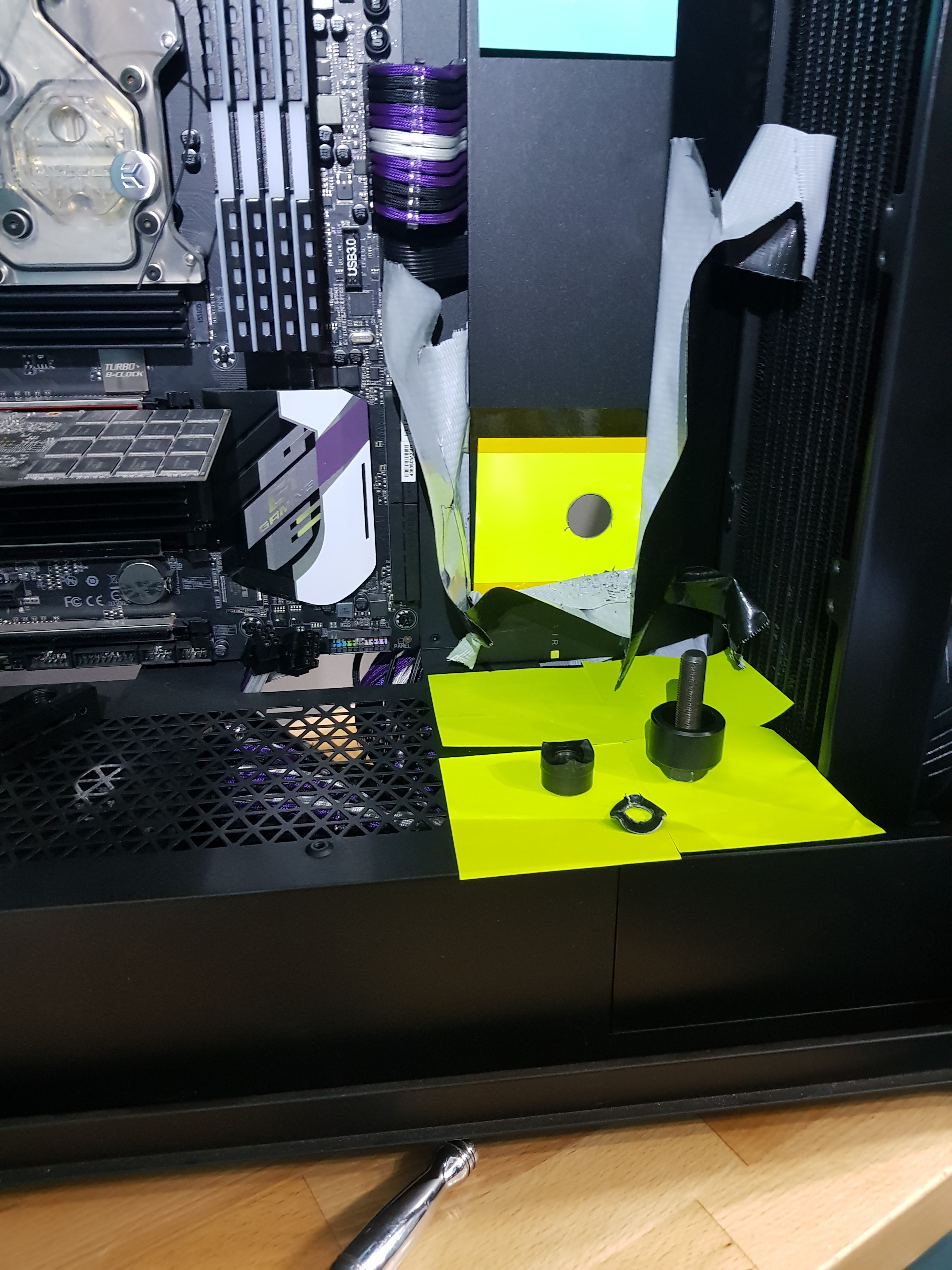
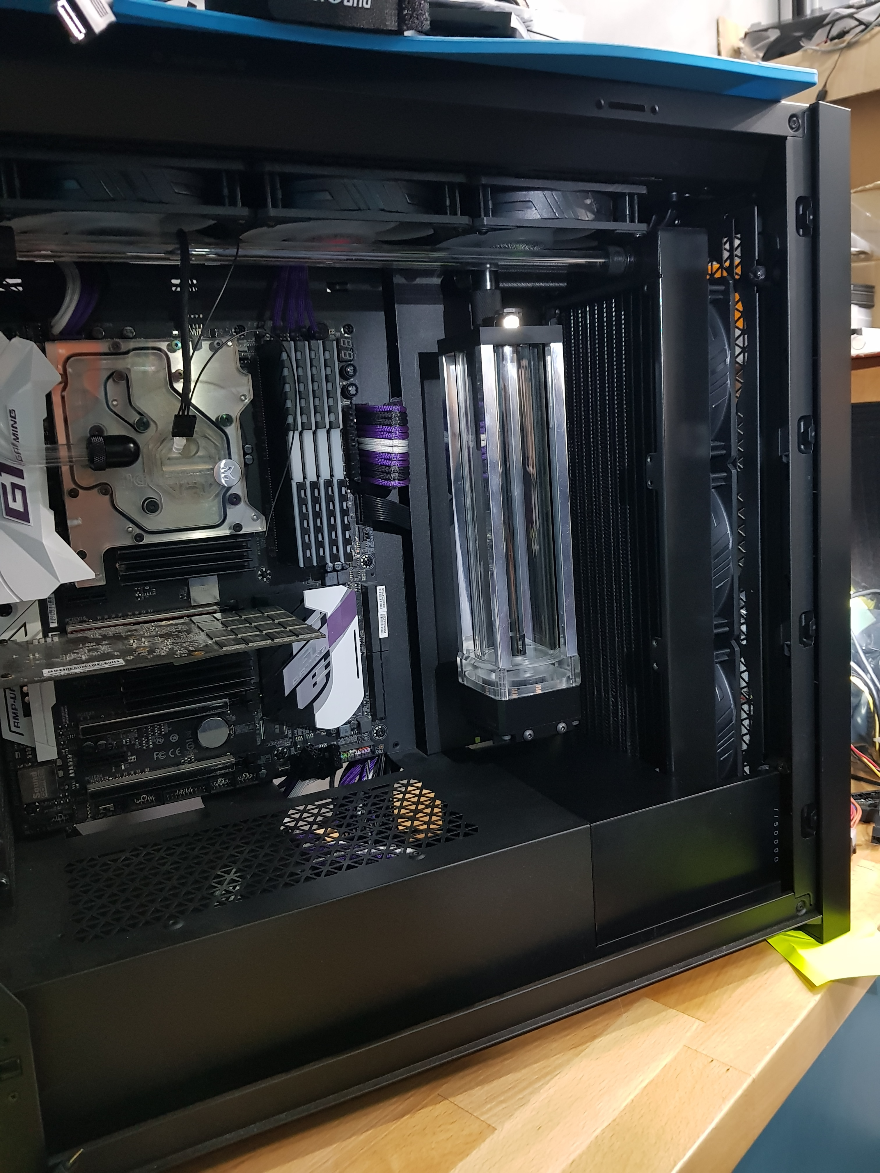
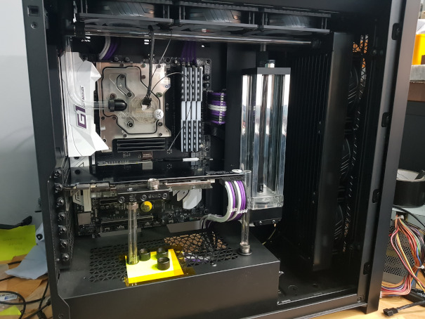
Right, first up we have the pass-through drilled and installed. Piece of tube is just for measuring the bends-to-be. Donor PC has now been stripped so we have the GPU in place with some luverly-looking power leads :D It's a good job I remembered to carefully account for the length of that GPU when I was mounting the res or it may only JUST have it! Good job I didn't forget aaaall about it and just centre the res on the backplate behind it! :eek: There's 12mm....but as they say, clearance is clearance :D
Need to bend a tube from the shroud to the GPU and from GPU to CPU (inlet is hiding behind the dangling LED)...but I'll get to that in a sec.


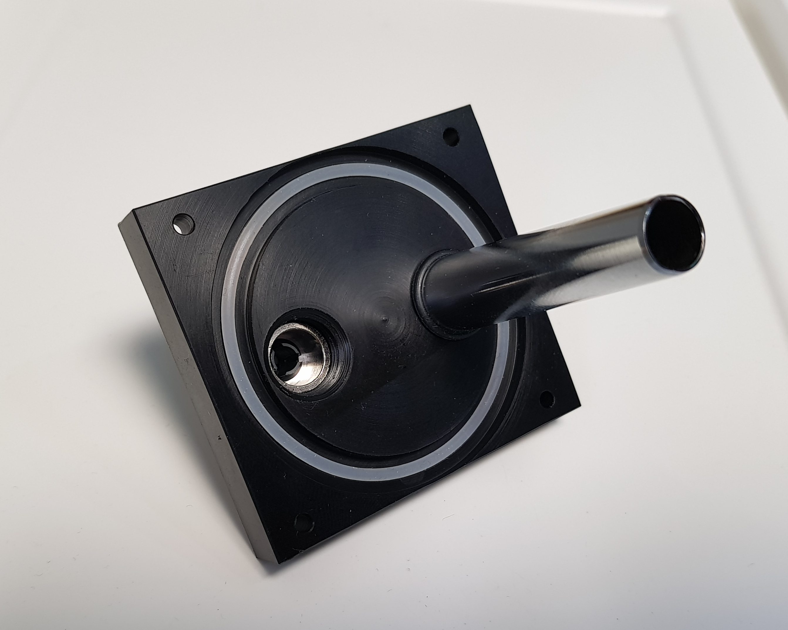
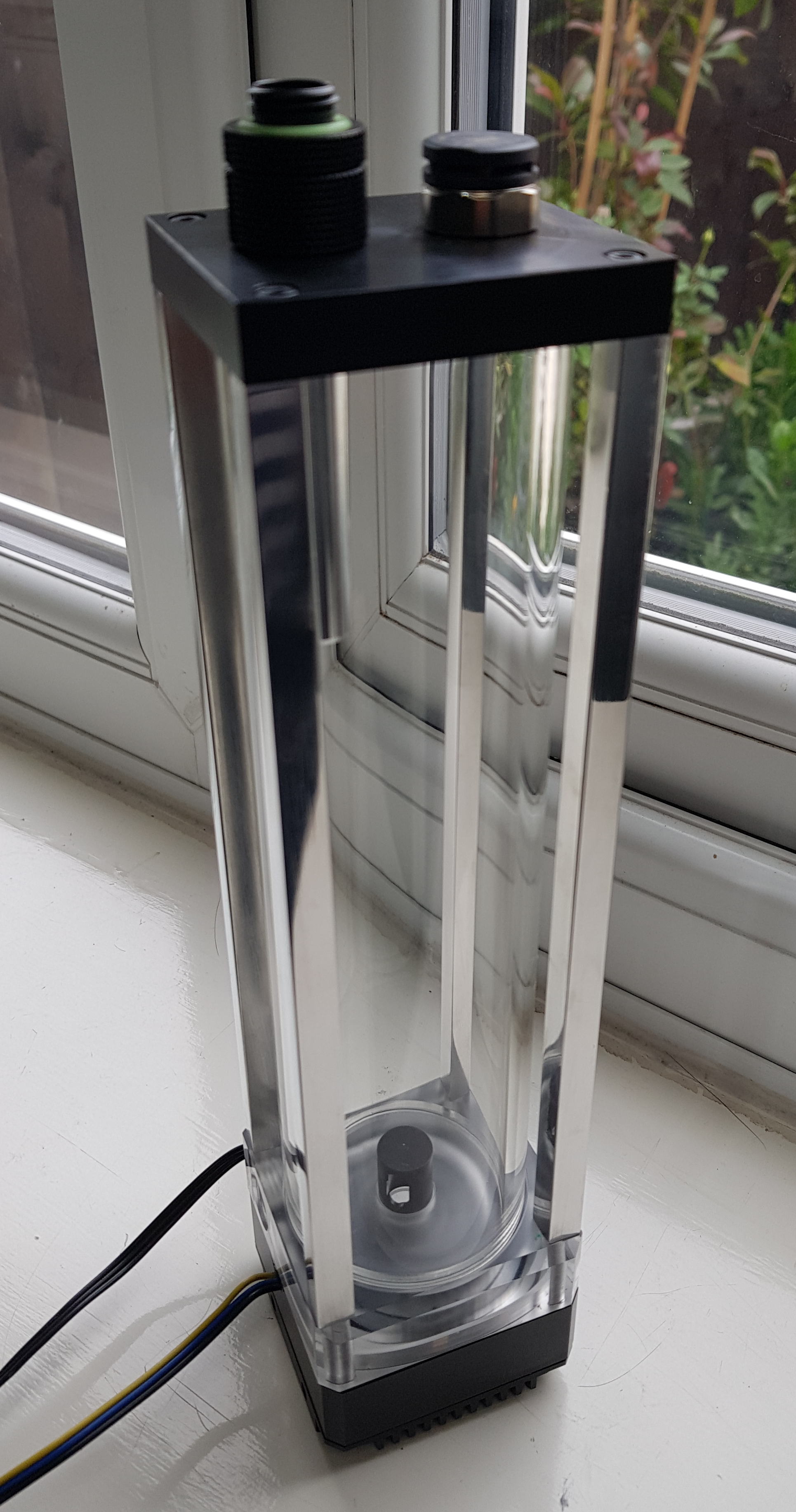
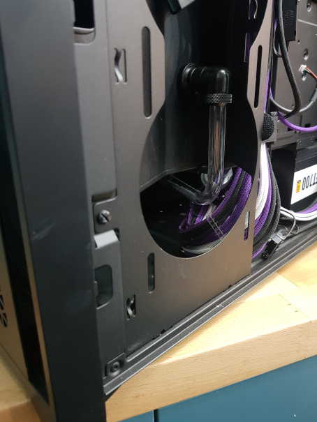
Under the plastic clip-on bit is the drain. For once in my builds, this is actually at the lowest point! :eek: :rolleyes: 
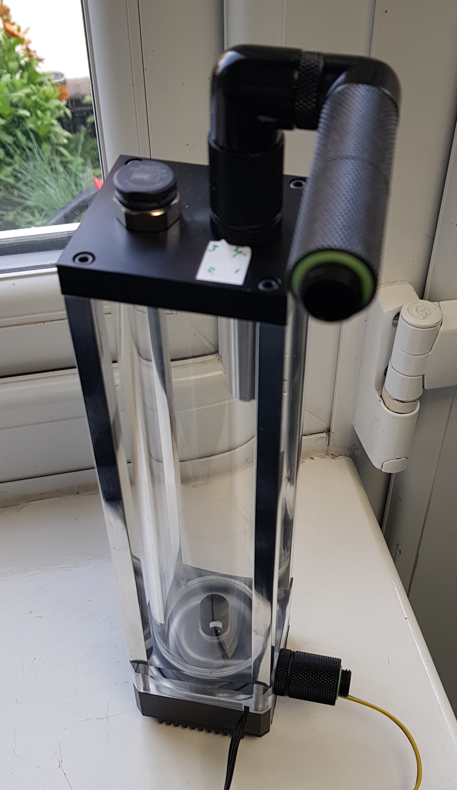
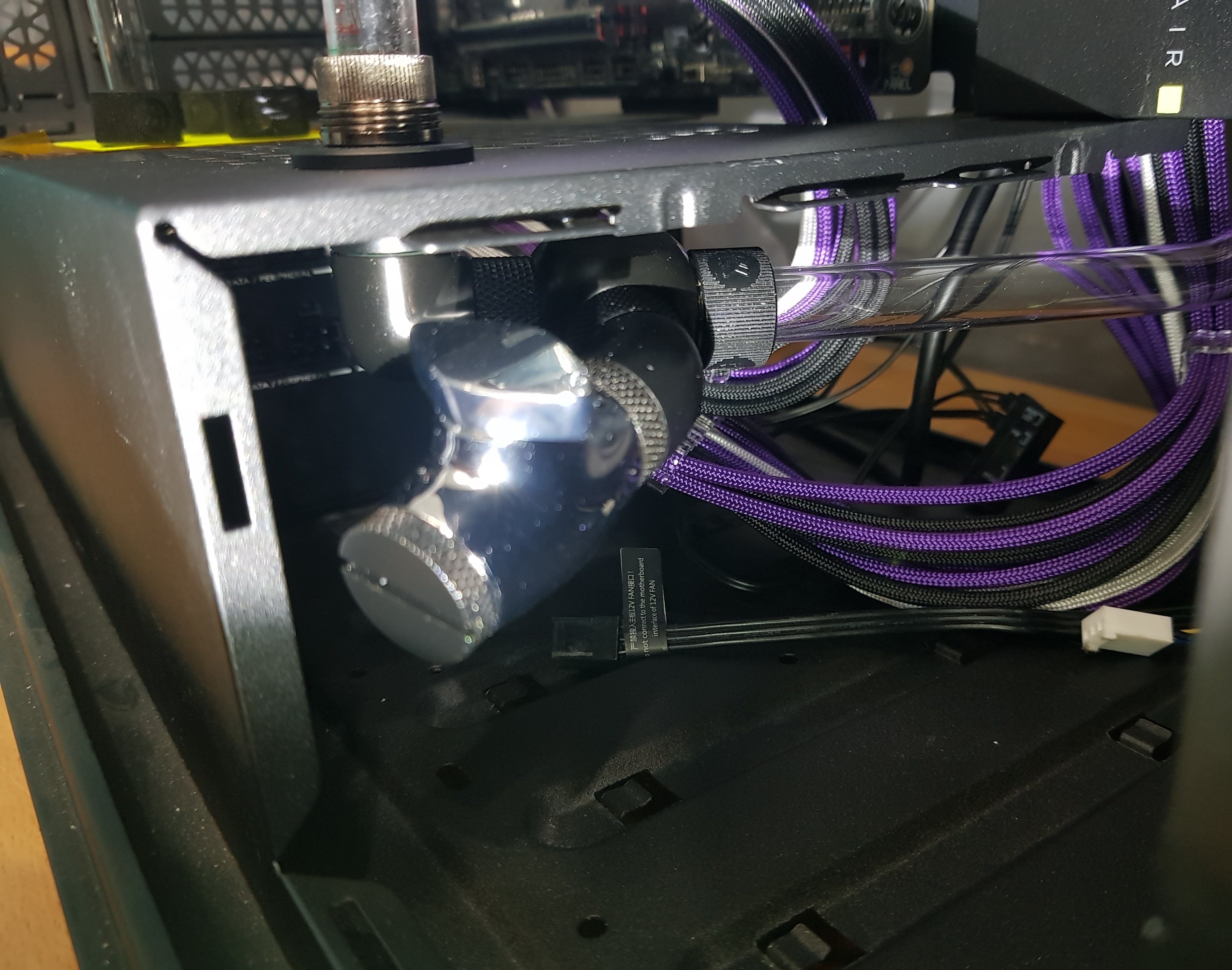
That tube carries on....


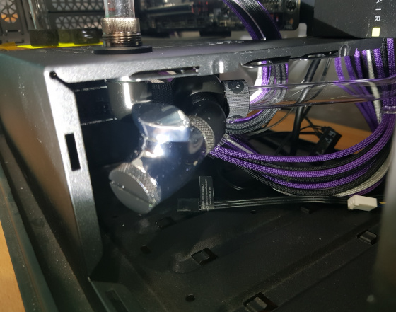
...and after a nice 90° bend (unlike the 88° first attempt :rolleyes: ) connects to the outlet of the pump.


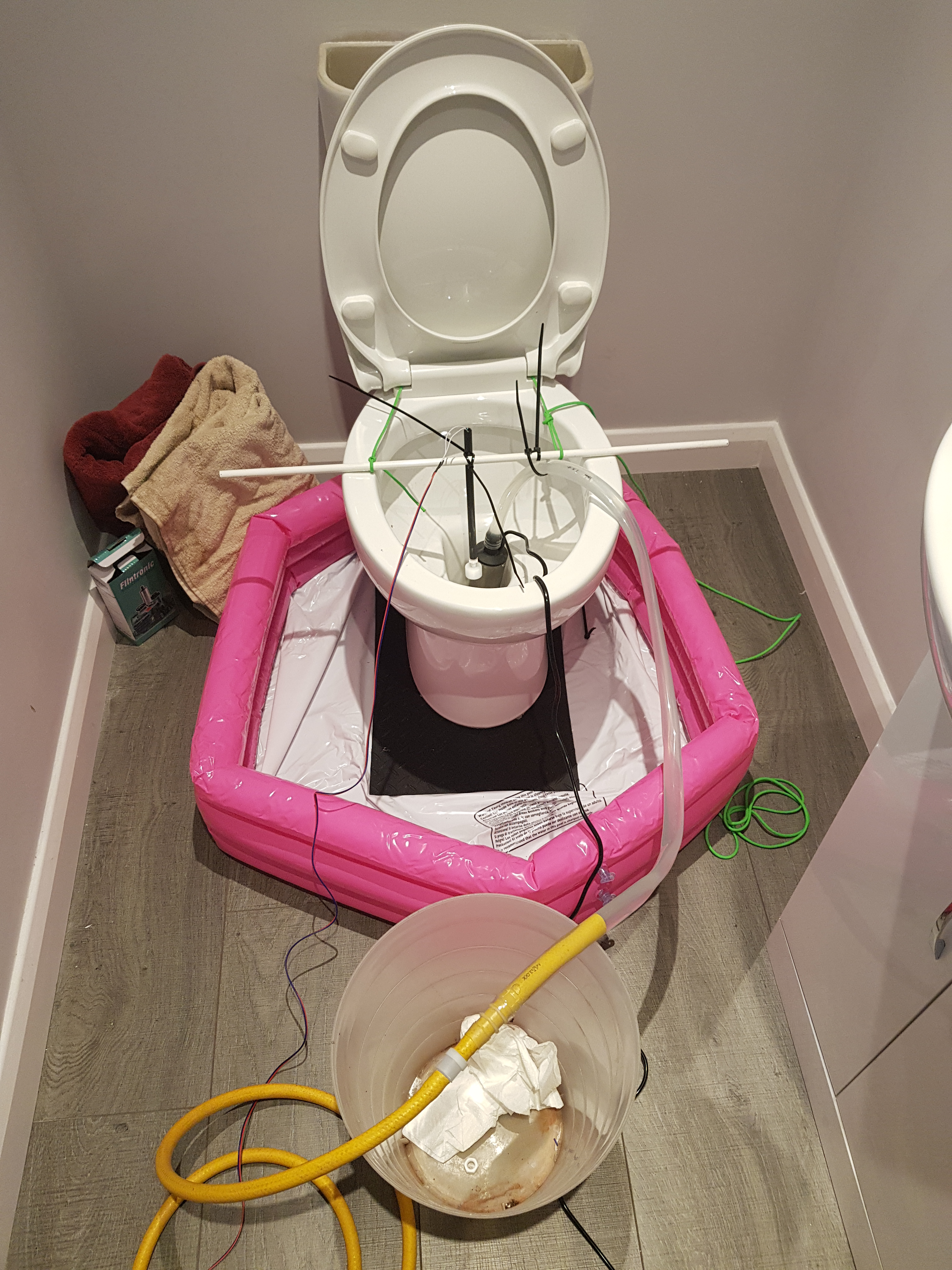
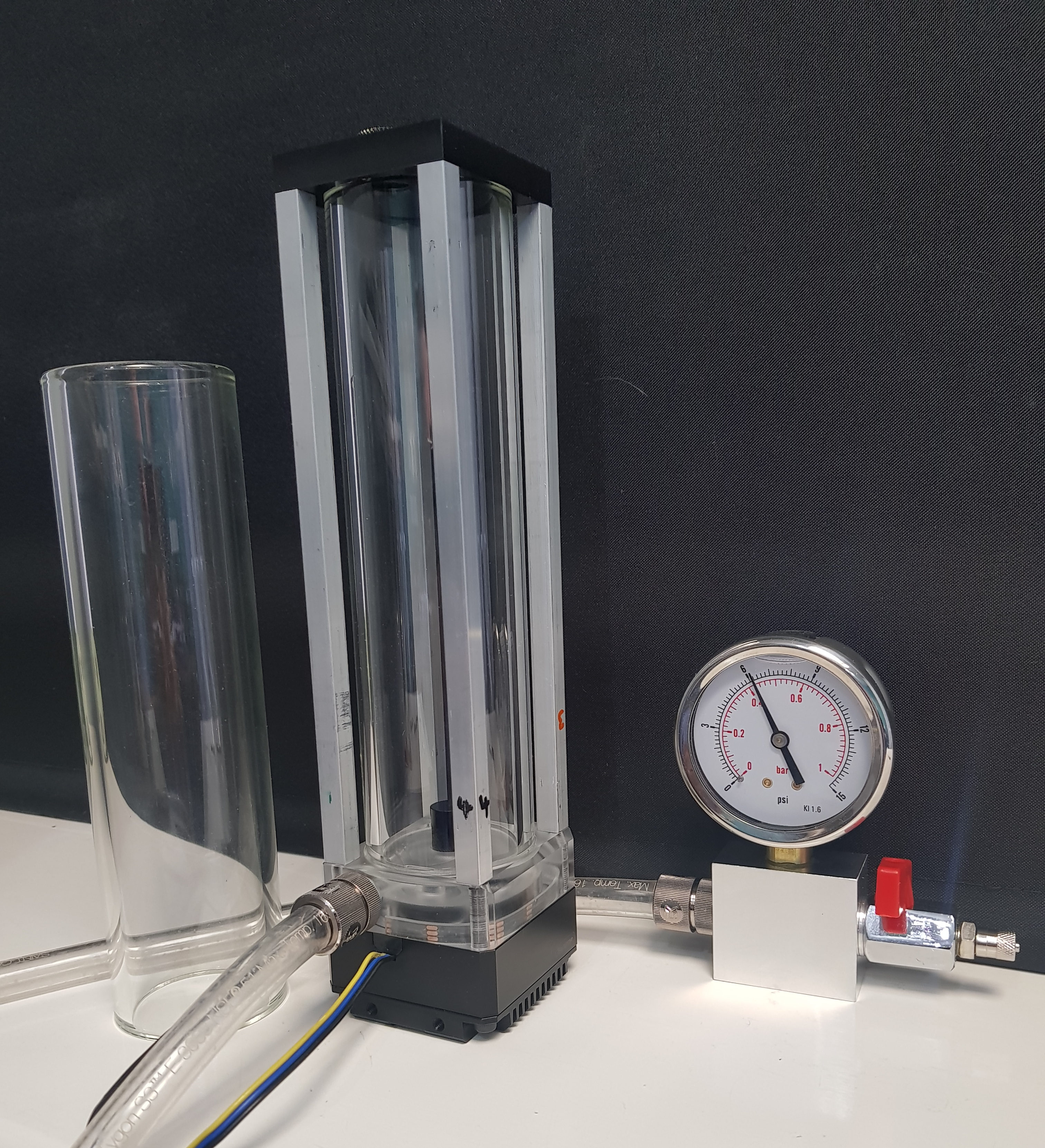
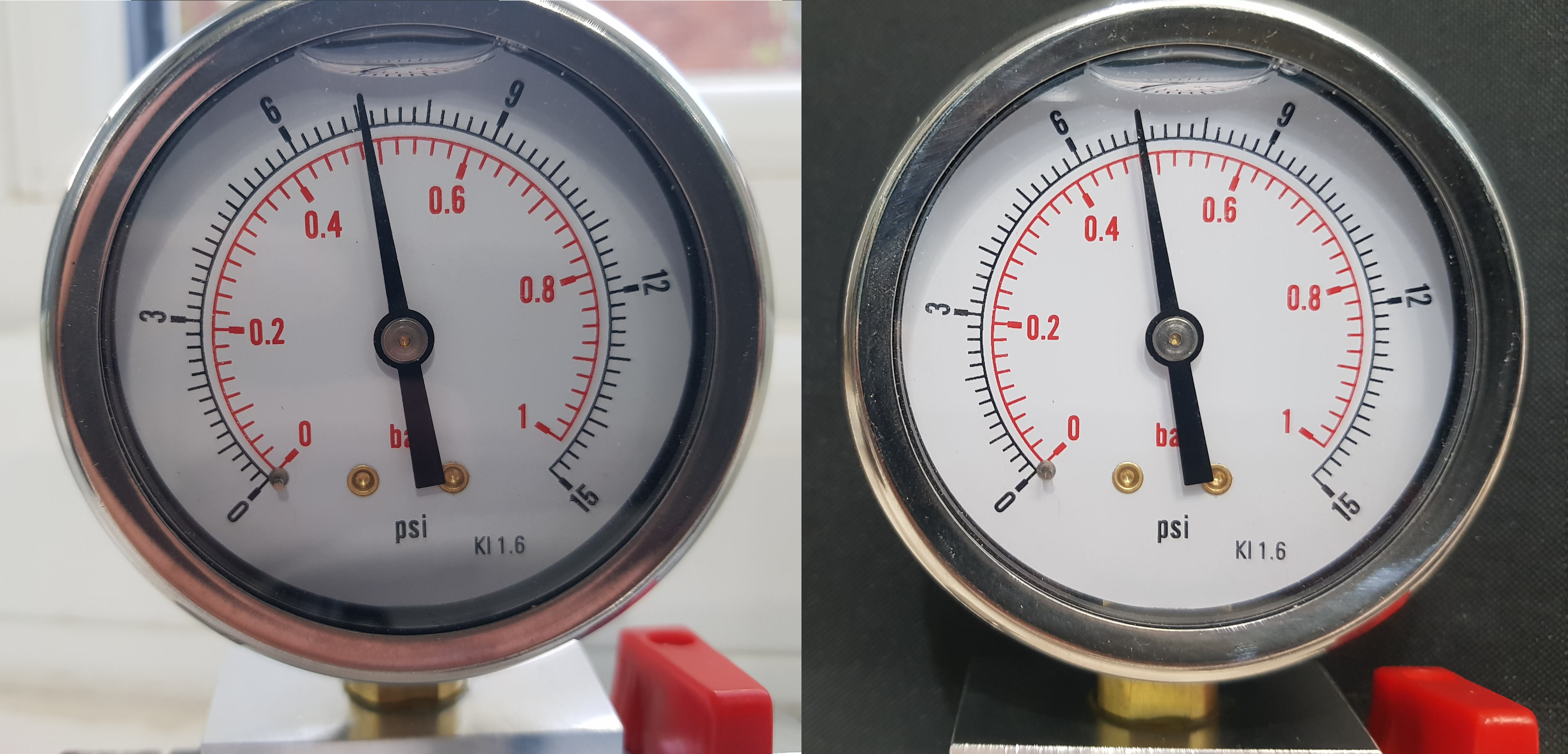
I plugged up the CPU, swapped the res' pressure-relief mebrane for a stop plug and hooked up the pressure tester last night. So far, this is all good. The top joint (the D-plug) where the res hangs from the fittings did spread a little but nowhere near letting go as it's restrained by the bottom fitting. In actual use it won't spread like that as the aforementioned pressure-relief membrane will....er, relieve the pressure.

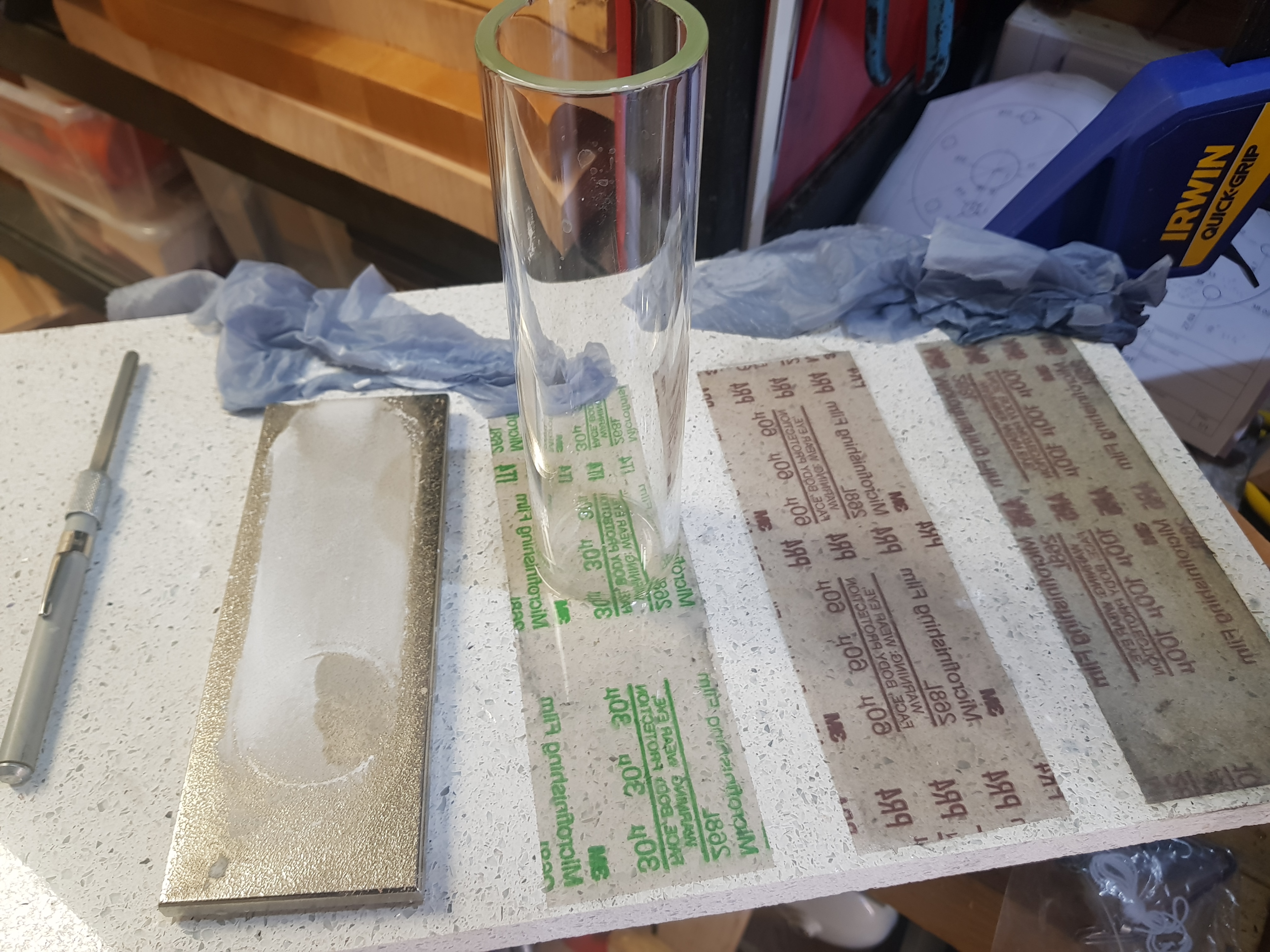
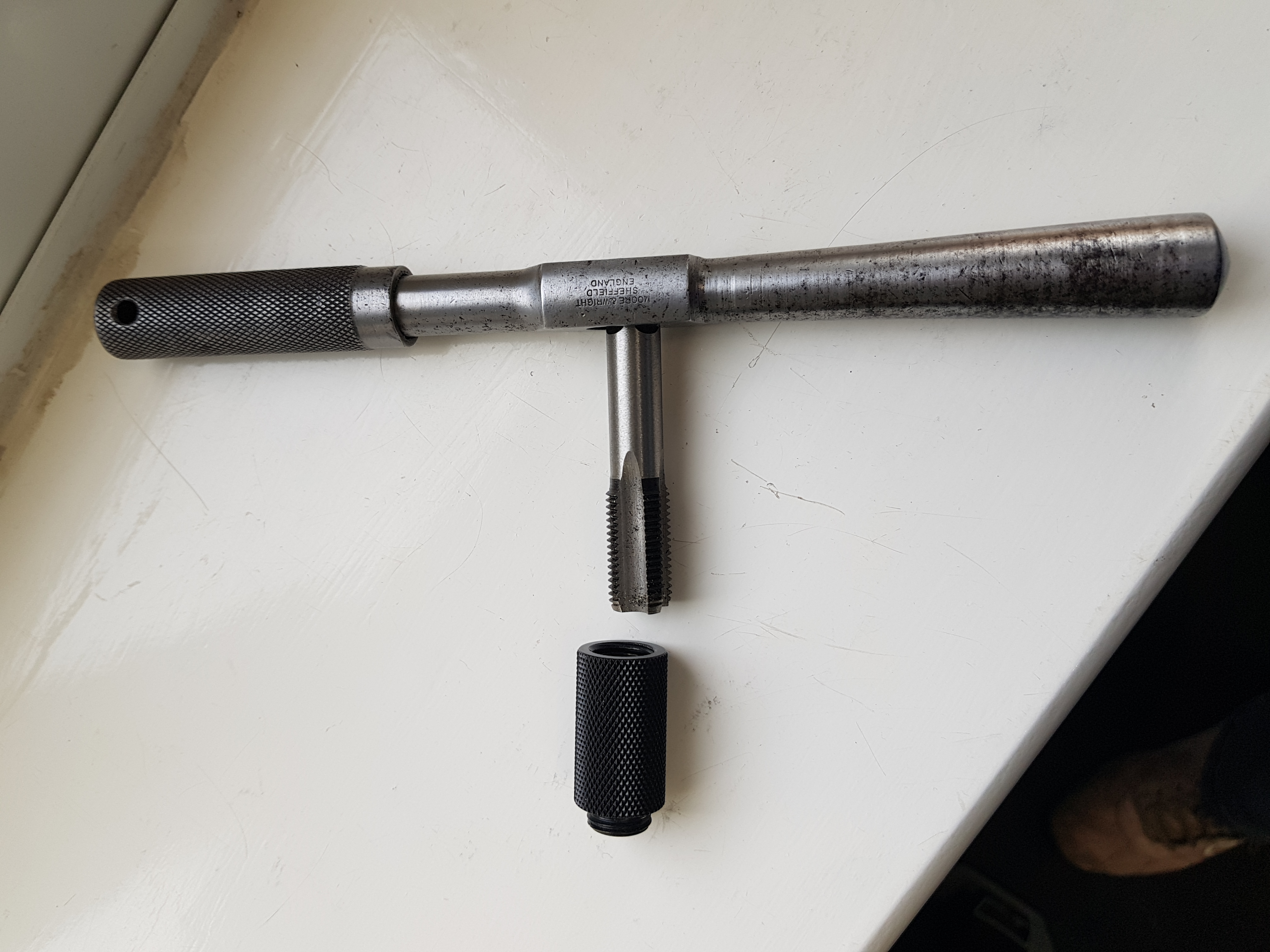
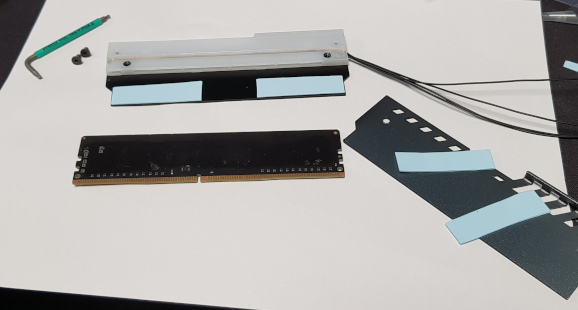
Now, I said I'd get back to the tubes to be bent for the GPU...and there's a reason for that. I decanted my parcel tube of spare tubing and got out the spare 12mm lengths to have a go at making a mess of the next bends. Odd, they don't fit the mandrels....ah, these are 13mm tubes and won't fit the fittings *facepalm* Se we're mostly on hold until OCUK post me some more. You wait, they'll hit the post just in time to get caught in another strike :rolleyes:

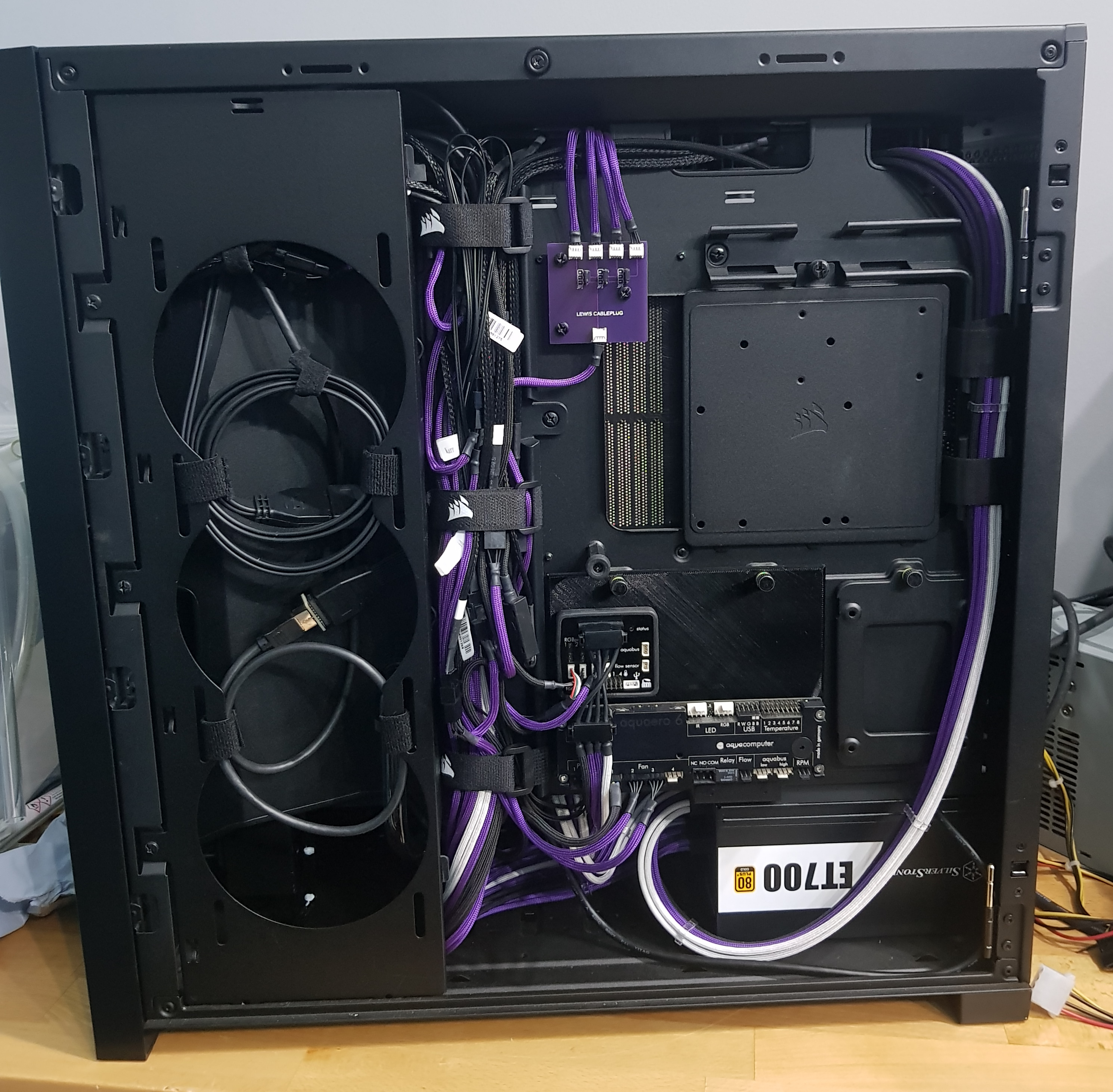
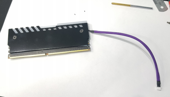
Aquaero is also out of the donor PC, the screen removed (don't need it) and the slightly redesigned mounting plate being printed on the 3D printer. The holes weren't 32mm and 137mm centres, they were 31.5mm and 137.5mm or something like that. Not the round numbers I'd approximated at without removing it from the donor. I also need to allow some countersinking (not enough space behind the plate without it) at the back for the screws to go through from there instead of threaded holes like I'd planned.

So things are moving along...but delayed. You'll know the tubing has arrived when you feel the colourful language flowing in abundance.....as I fail to get the bends in the right place. The run is about 300mm and I've order 4x1000mm lengths....I have THAT much faith in myself :D
 
Hadn't realised everything around it was black. Have you thought of black for the reservoir support struts?

Only kidding! That looks really nice - love the floating design for the pump mount.

Too soon! :p;) I've marked one of the struts slightly when I put the GPU in. It won't really show though.....MUST...RESIST...UNNECESSARILY...RE-POLISHING...IT!
 
This is a cross-project quote from Project Dividend - just to avoid confusion:
Don't worry, I'll sort the colours soon so it doesn't look like a Unicorn threw up inside it

Fear not, I have done some more wiring (and sleeving) so that more Unicorns can be unburdened! For your delight, a really badly mashed together anigif showing at least some of its *cough* glory! :D


(click for larger version if you can stomach it :p )

Two ARGB LEDs now installed in the CPU block, two in the GPU and a strip in the pump top.
 
Gah! Arcylic turned up and I've made up the CPU-GPU link. I thought it was straight in line so I could just to a simple 90° bend, trim the ends to length and be done with it...but no, there's an offset. I've put a kink in the tube and got a piece that fits....but I'm not sure if I'll remake it or not as it's not perfect. I've made a few failures for the bottom S-bend link and given up until a new mandrel turns up. Mine has been sawn off for a bend that had to be close to another at some point in the past. I keep getting 92° bends out of it where it just doesn't quite sit all the way down. I've also got a few bubbly bends (over heating), some slightly squashed bends (didn't heat far enough back past the bend), some re-heat & try again manglings and so on. Once I get a mandrel that might do 90 more reliably, I need to add about 4mm to my measurement to get the bends spaced correctly apart - it's moving in the mandrel as I do the bend and they end up too close together.....and then at 92° to add insult to injury.

In the meantime, I've replaced the GPU cable combs you can see in the rainbow obscenity. A couple of 14-pin combs rather the separate 6 and 8-pin. Makes it sit more as one cable than two so it looks nicer.
 
Some work on the rear compartment. Power cable for the Aquaero and Farbwerk 360 now made. Fair amount of swearing involved! The IDC style molex plugs seemed a great idea for low-profile wiring and not having to double-pin to chain them together....but really awkward to get the wire in and the covers aren't designed to come back off....so if you find that you've been a muppet and put the plug on the wrong way round....swearing.


Once tested, the door (solid) can go back on, then the case panel (also solid) and everyone will be able to admire the effort I put into making it (fairly) tidy! :rolleyes:
 
Back
Top Bottom