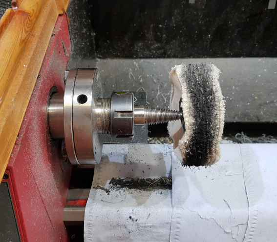
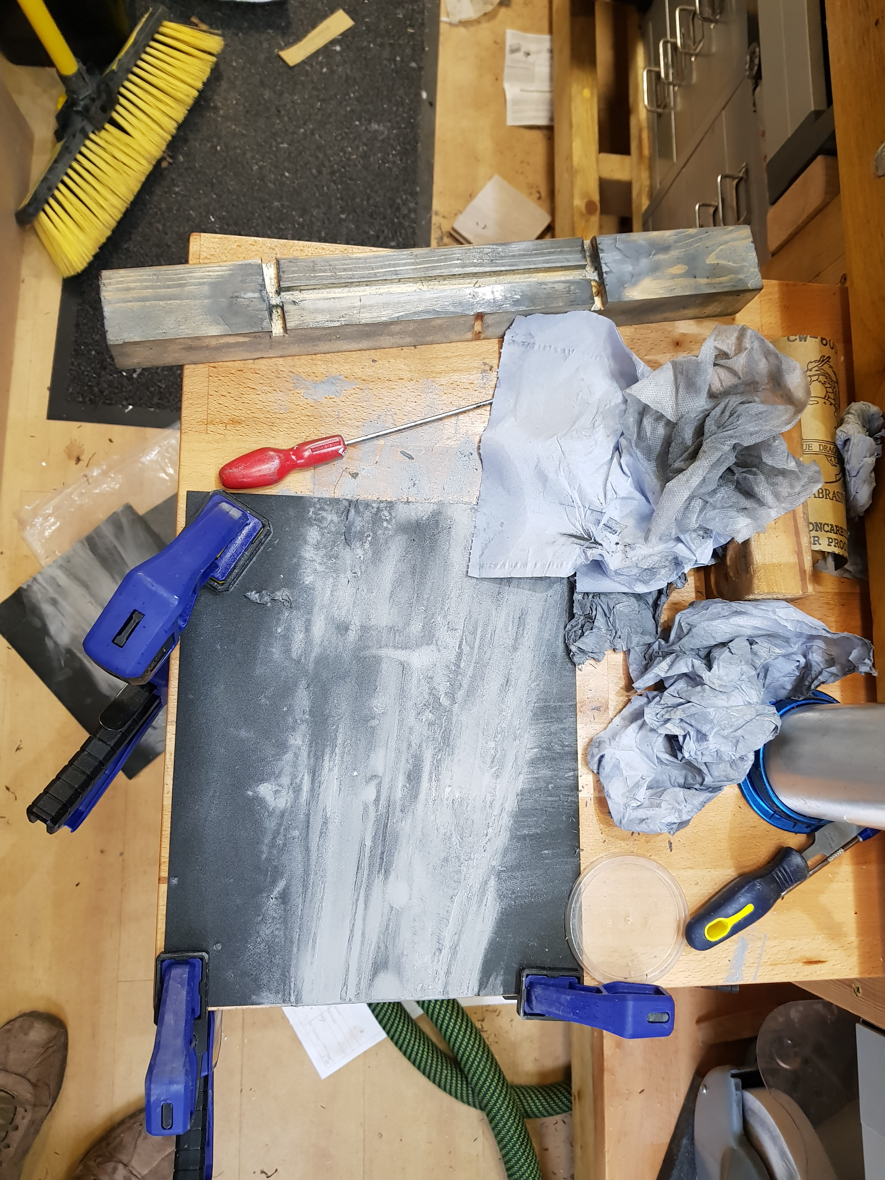
Ok, so I've succeeded in making a mess!

The chunk of wood you can see is where I quite quickly made a jig to hold the bar while I lapped the sides. My fingers hacked one bar but there were three left to go! The slots to the side are to pry the bar back out again - no prizes for guessing whether this was an afterthought!

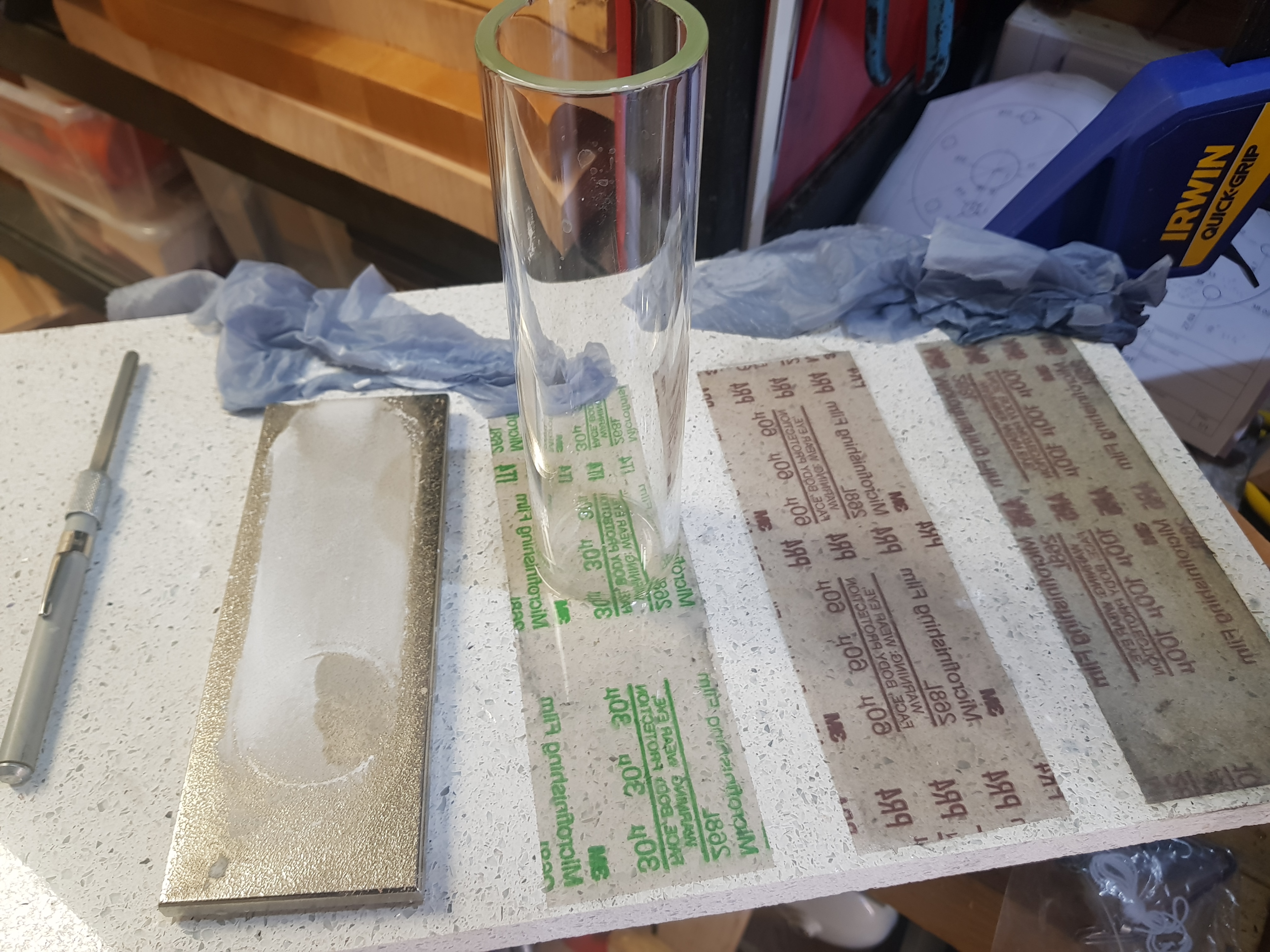
That's 320 grit using WD40 to wet it - which helped stop it clogging up quite so much. Should have then gone to 600 grit but thought I'd get away with it after a much smaller test piece.
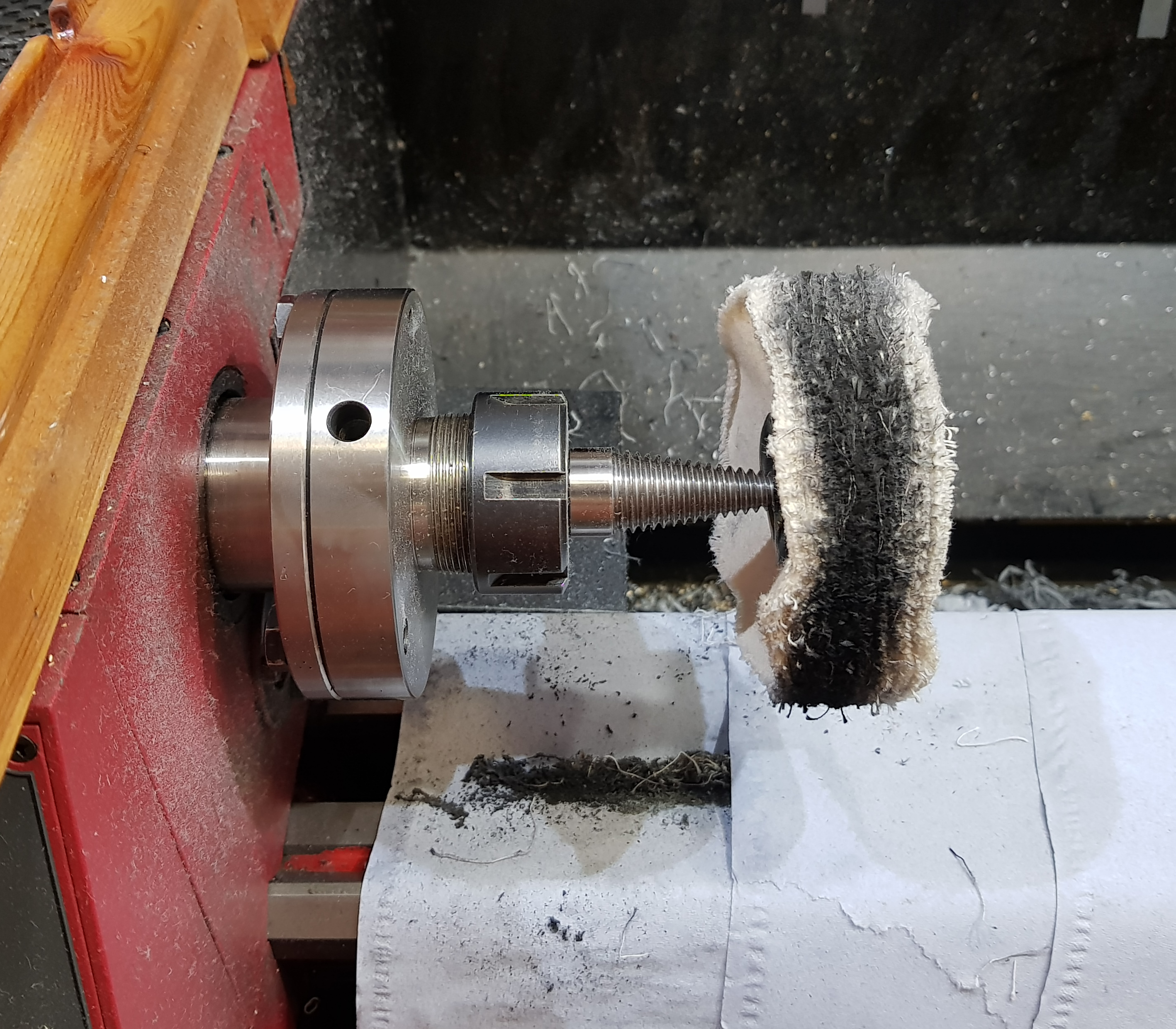
I tried blue compound but ended up finding the brown to be more effective - certainly faster and that was really much criteria
Then I gave it a final buff with some pink. All on separate wheels so as not to mix the compounds. The wheels are mounted on an arbour in my lathe....which now needs a good clean too

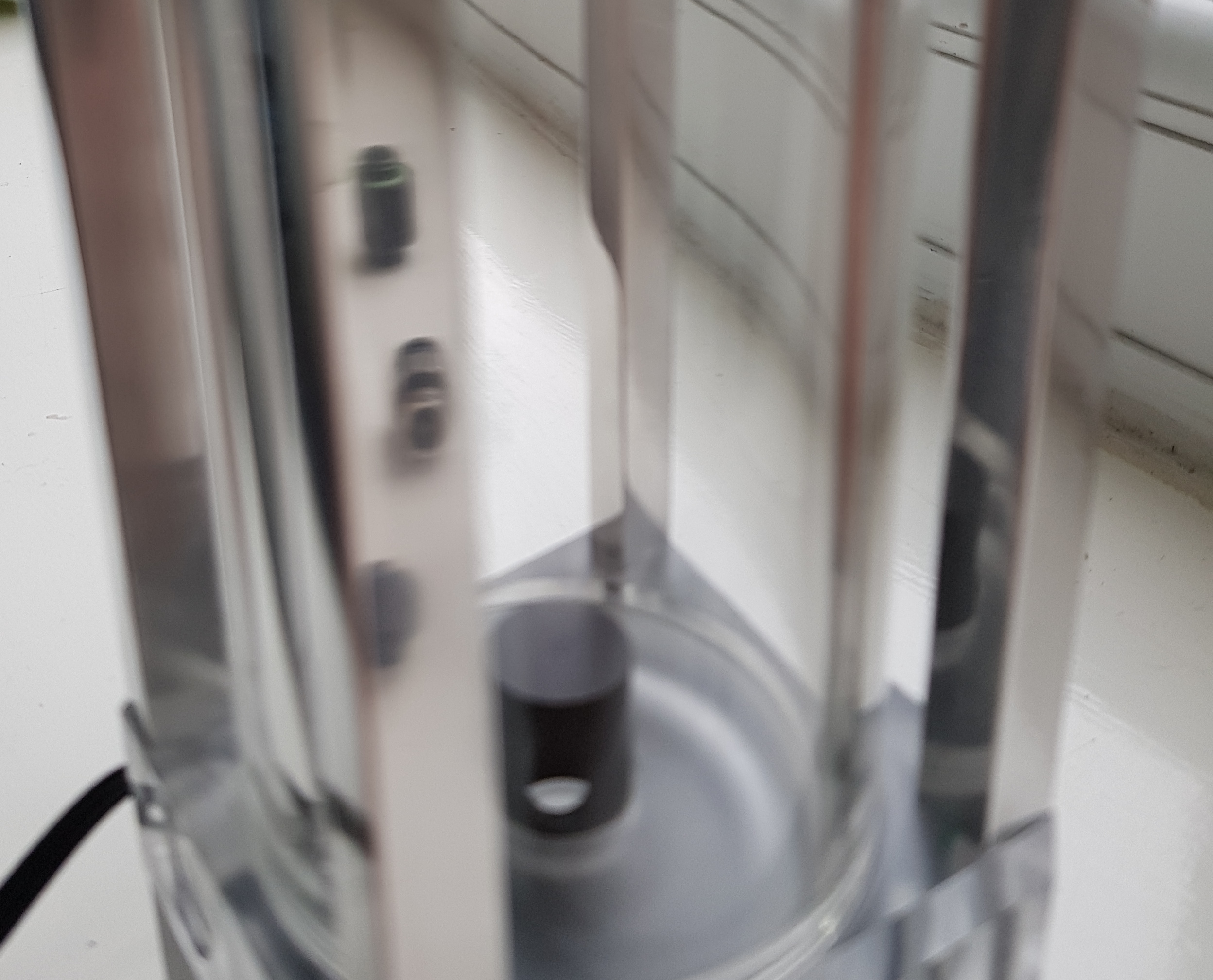
Howzat?! Well, to be perfectly honest with you, it's not quite as good as the potato pics make it out to be. You can see some scratches where I really should have taken it to 600 before polishing....but it's pretty good for a first go, I've learned some and I don't think it'll notice once mounted to be honest so it's not worth starting from scratch.

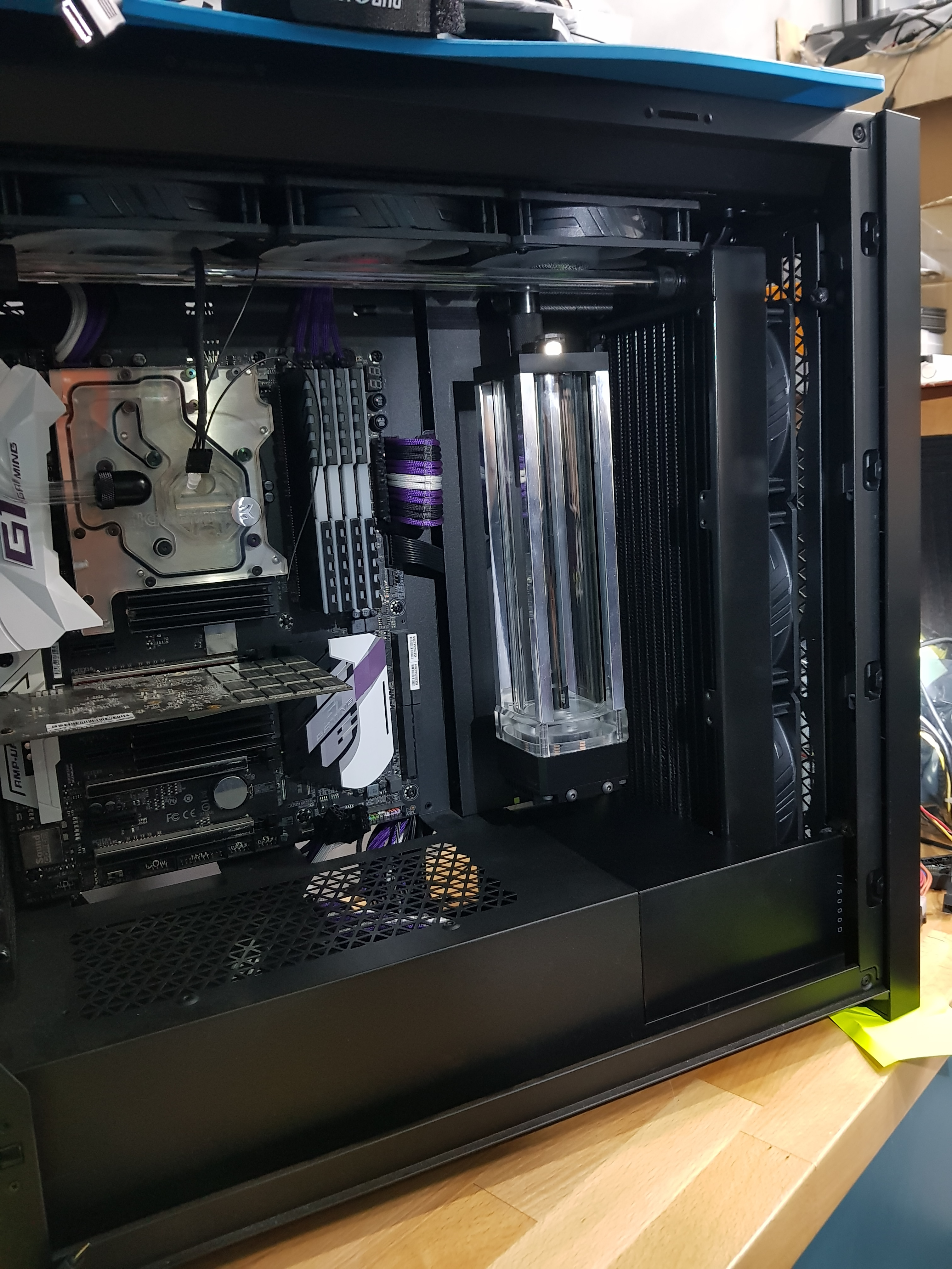
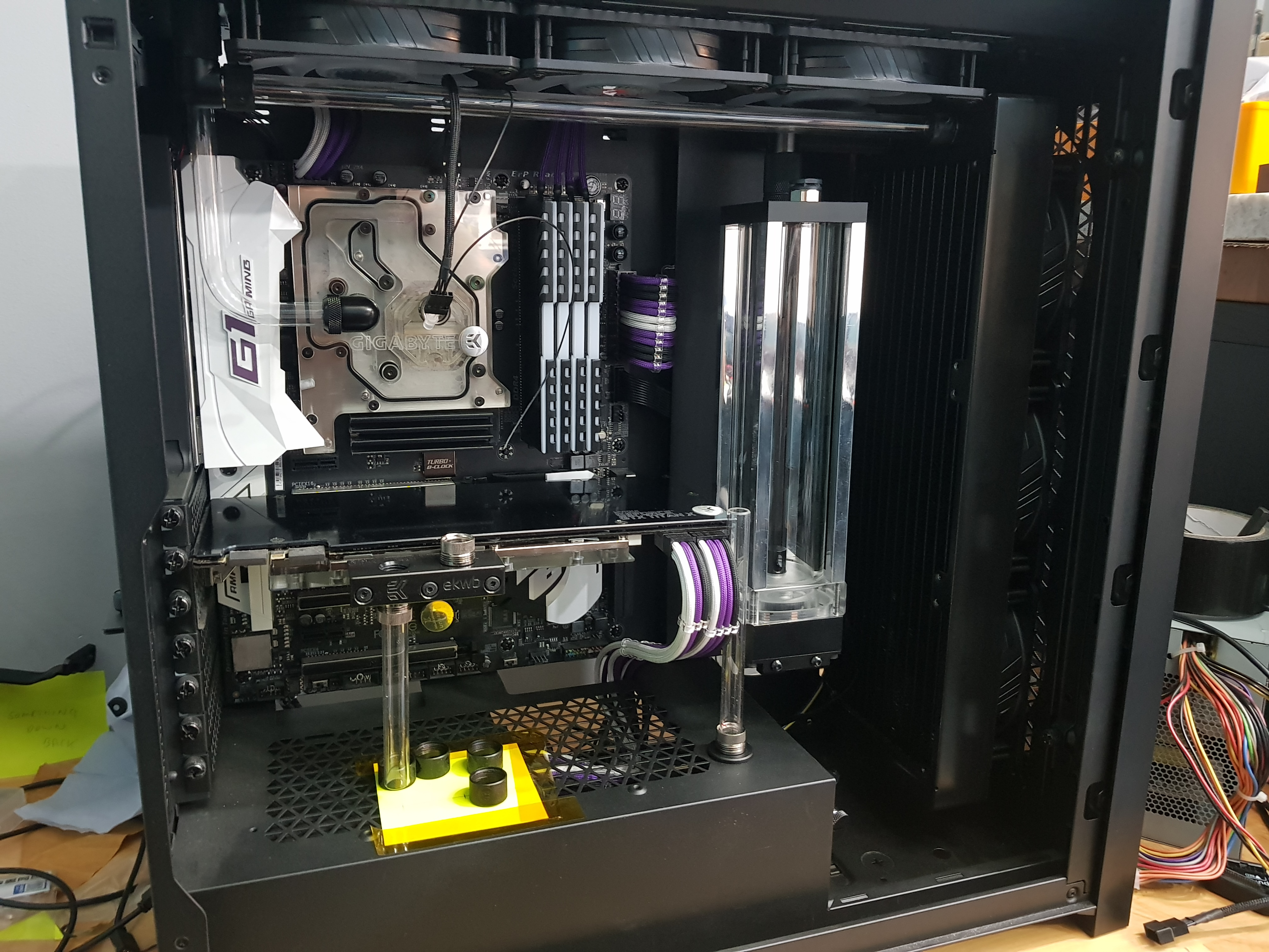
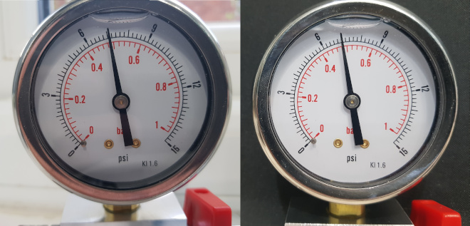
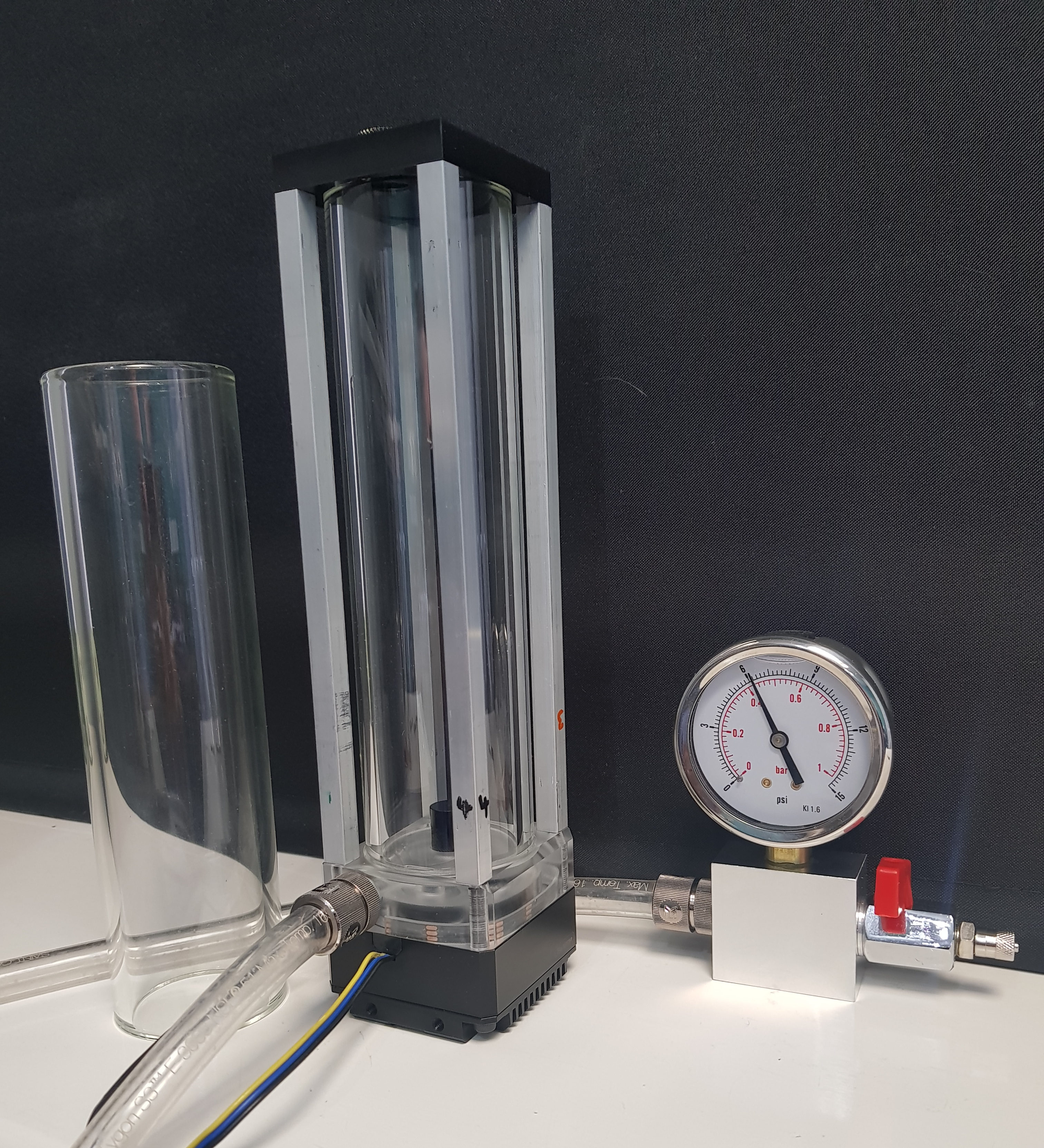
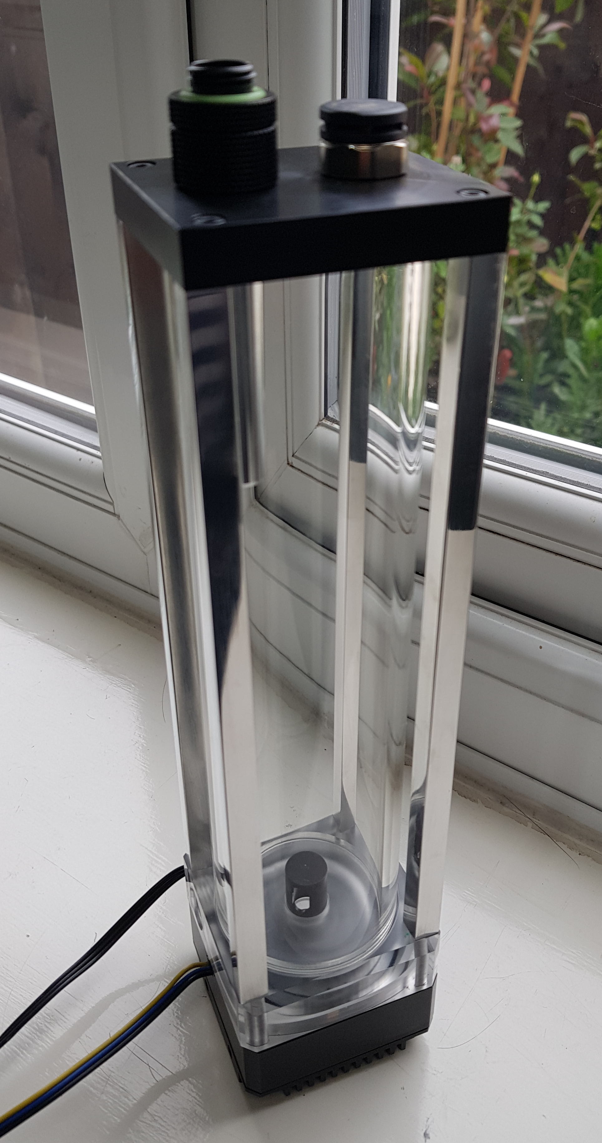
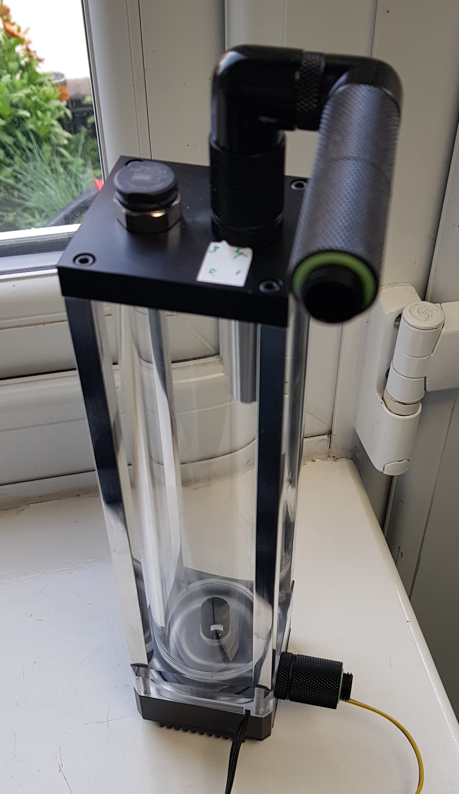
Fully assembled and ready for pressure test - which I did before this pic was taken, so before swapping out the blanking plugs for the pressure relief membrane etc.....in case you were wondering
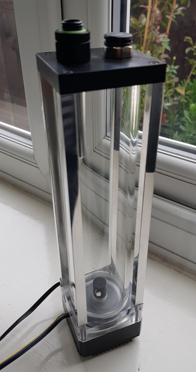
Initial pic on the left and 16 hours later on the right. That's what, half a psi over 16 hours? I'll take that! Also, well within the realms for temperature variation too - the first test before I lapped the glass actually rose in pressure.
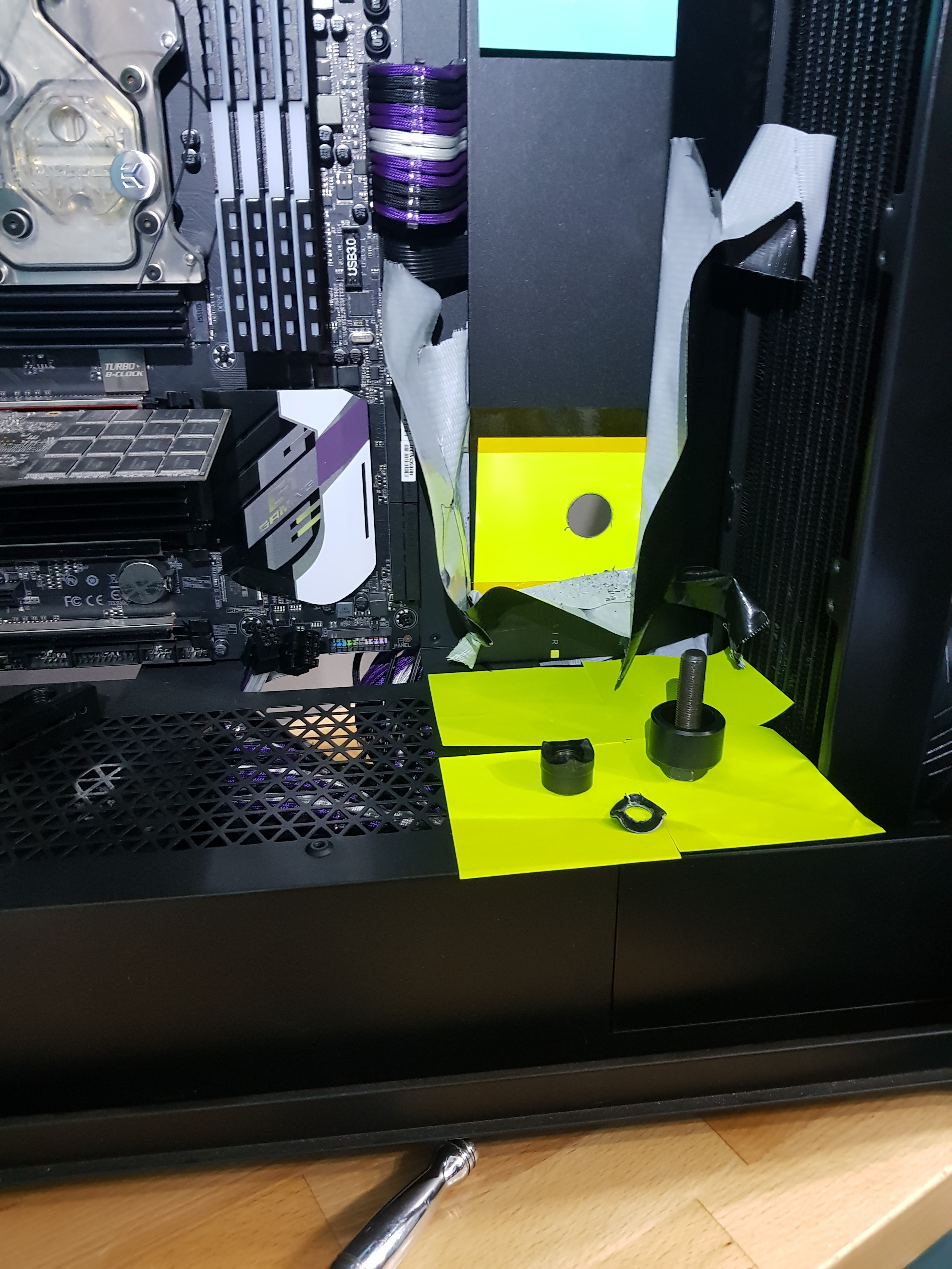
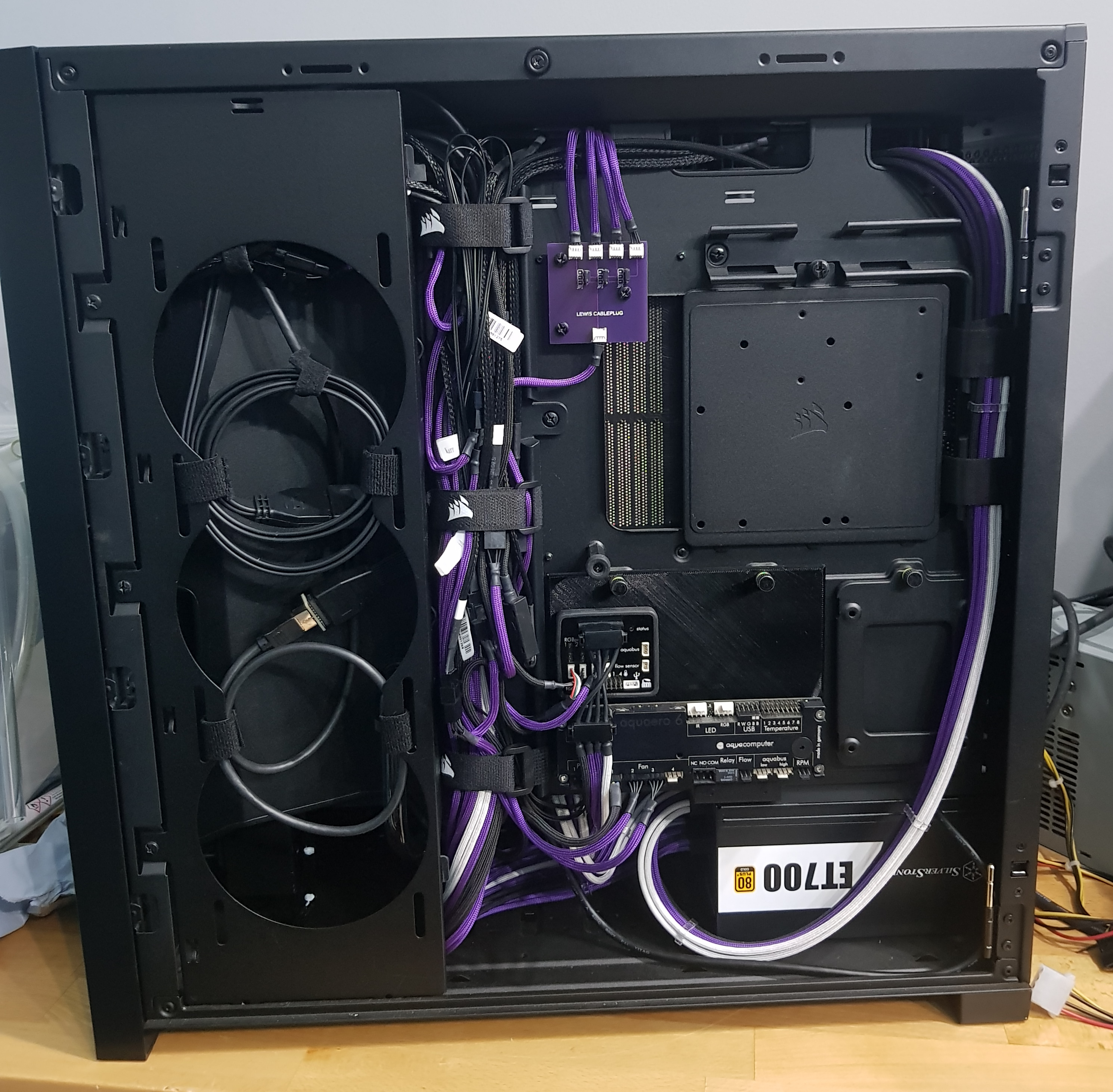
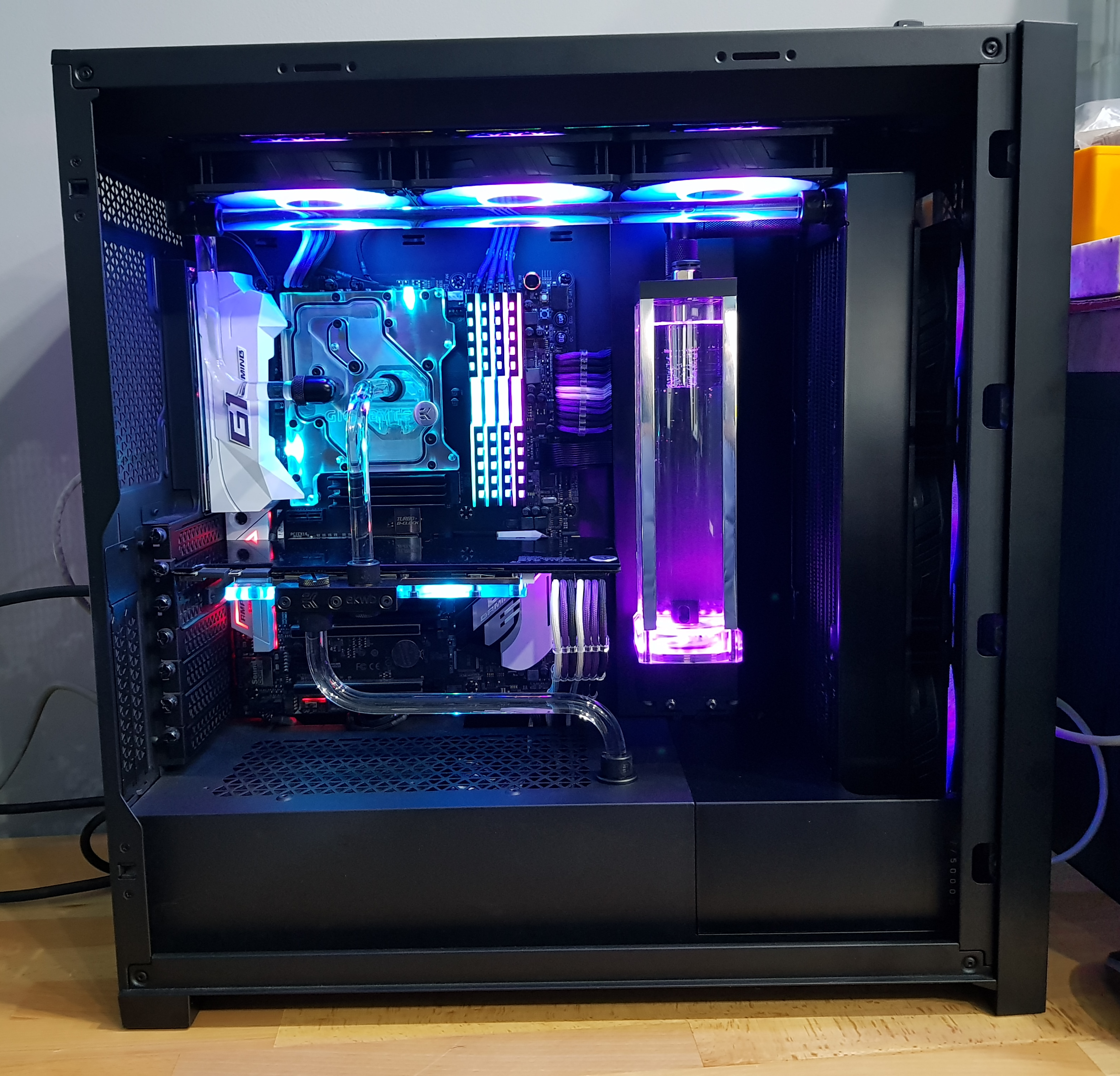
Right, now I just need to start punching holes in the case for some pass-throughs....couldn't make the pipework easy for myself now, could I!?


")

")

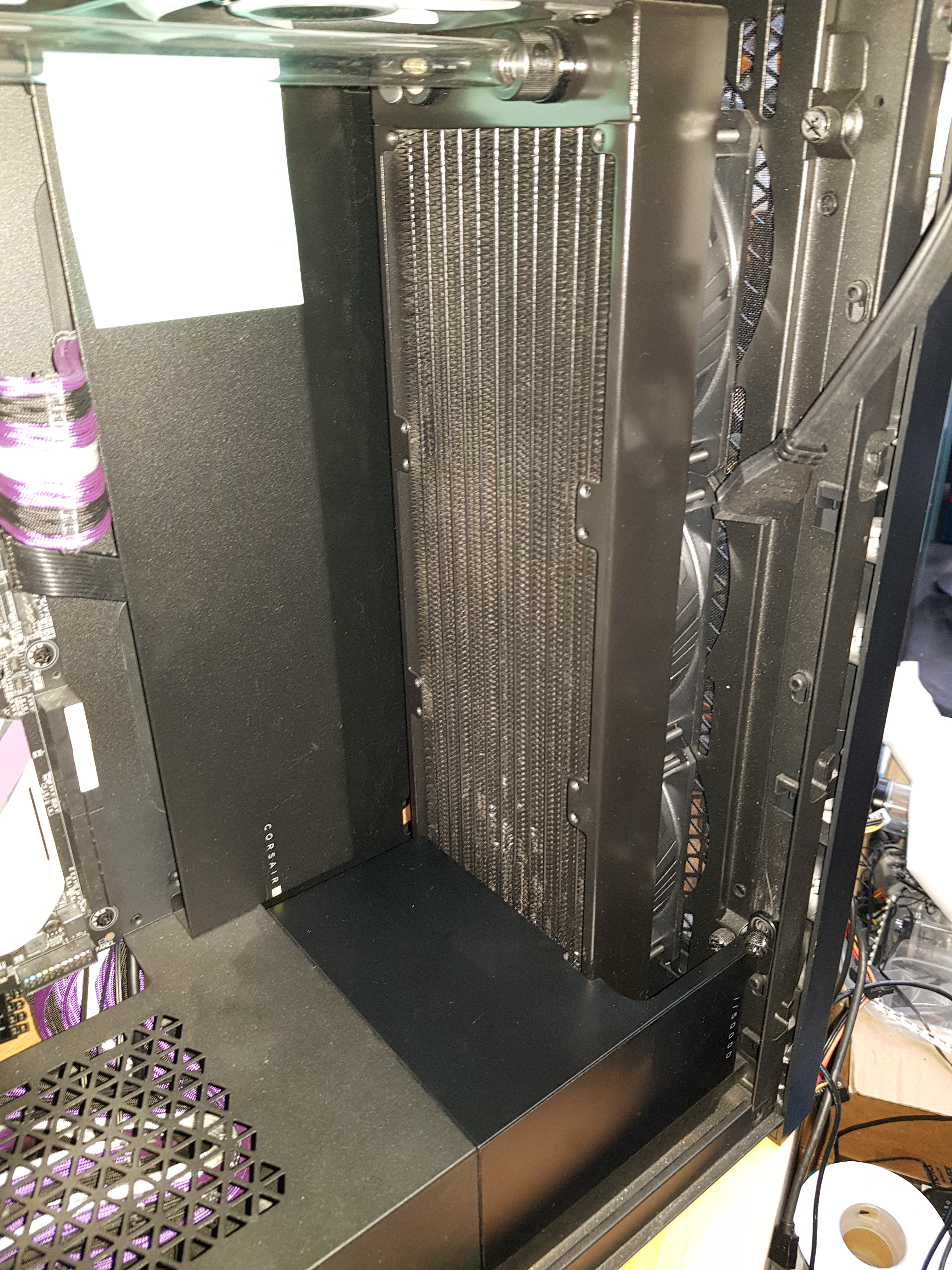
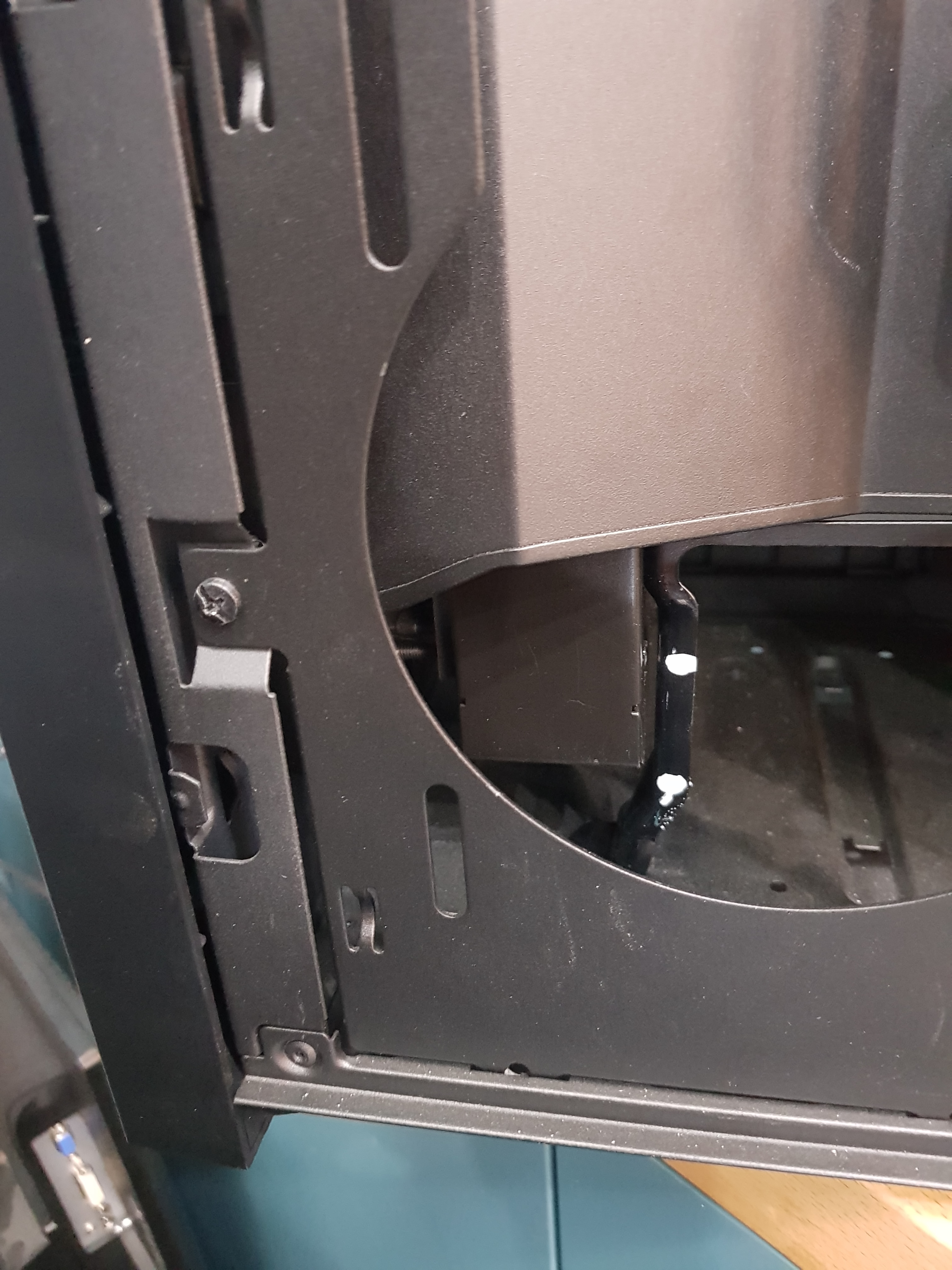

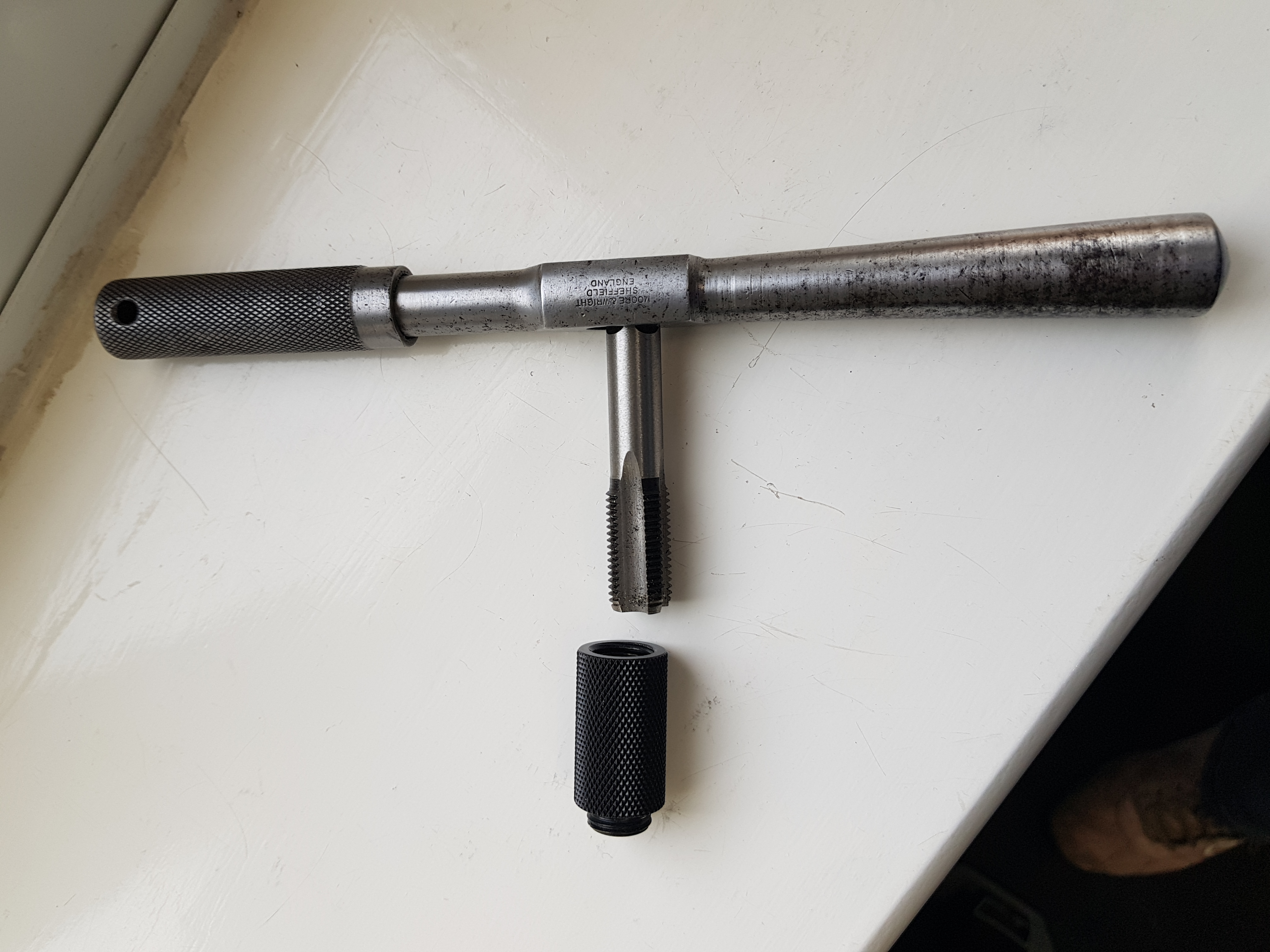
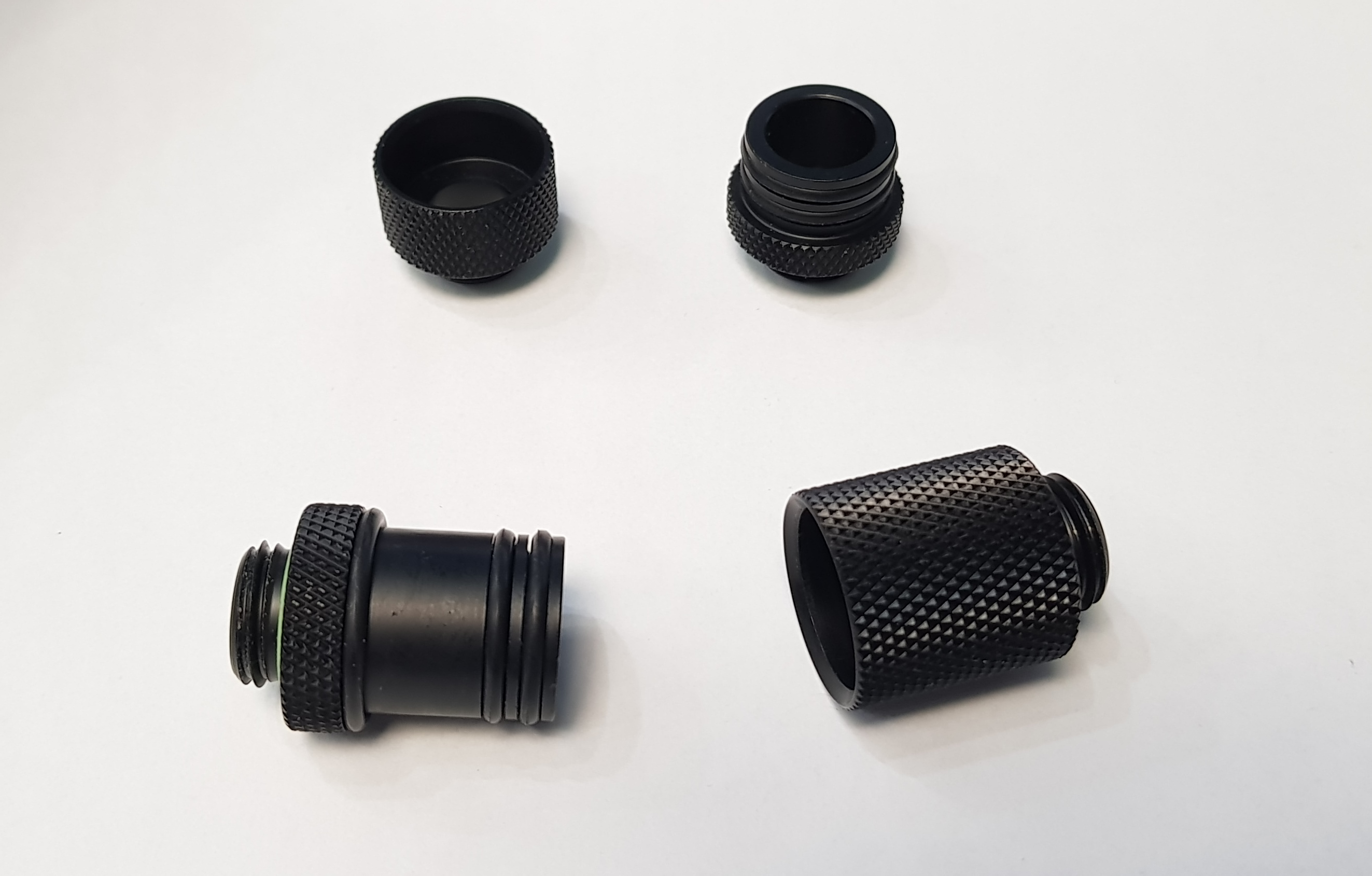
 Centre punch, step drill (normal drills tend to make triangular holes in thin metal) to 10mm and then a Q-punch (thing with a bolt through it at the bottom) to take it up to 20.4mm for the 20mm pass-through fitting. Then a spot of deburring to get rid of the sharp edges.