You are using an out of date browser. It may not display this or other websites correctly.
You should upgrade or use an alternative browser.
You should upgrade or use an alternative browser.
Ronski's Solar & battery DIY build with whole house backup
- Thread starter Ron-ski
- Start date
More options
Thread starter's postsSorted the clearance problem.
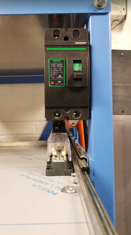
Pretty awkward to do though, had to drill a total of eight 13mm holes in the back of the box section, then fit M10 riv-nuts with little room to work in. The tool was 500mm long, the gap was only 530mm deep, and not much width given the shelving unit next to it, but its done now.
I will 3D print terminal covers for the breaker, all they supply it with it is a bit of rubber that doesn't fit very well.
Last edited:
Progress, slow but getting there.
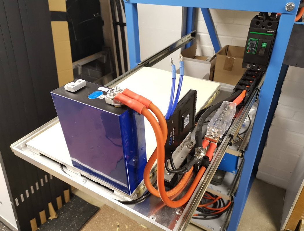
BMS mounted

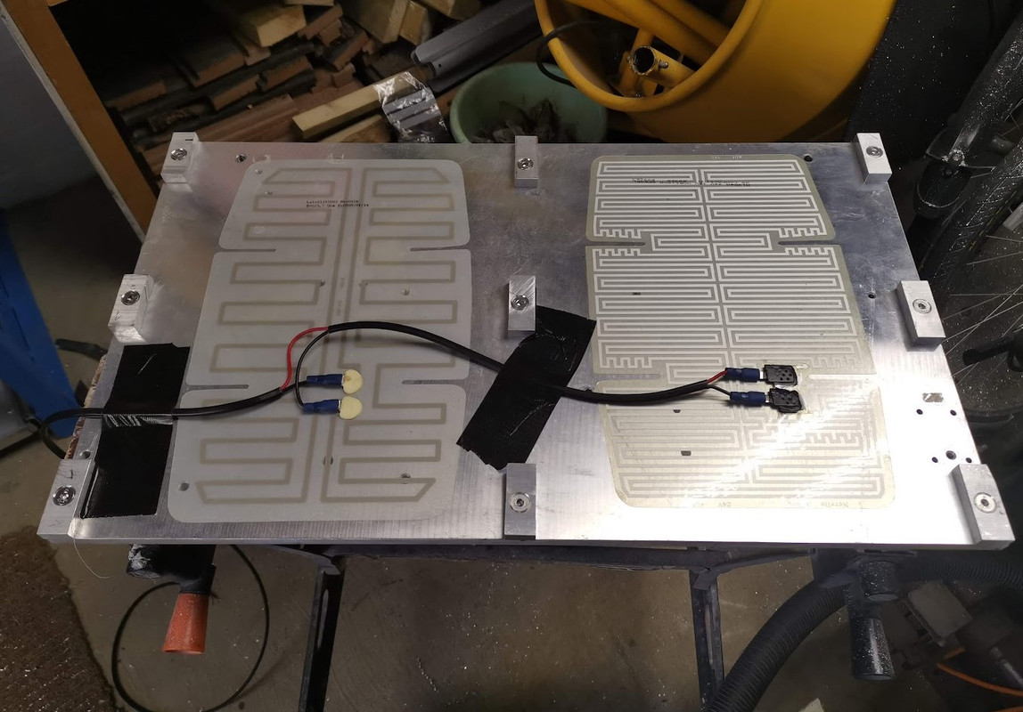
Heater plate - I was going to put a heater pad on the bottom of the tray, but that would heat the entire tray, but I found a bit of 10mm aluminium exactly the correct size, stuck two 24v 40w mirror demister pads on it for heating, and made some feet.
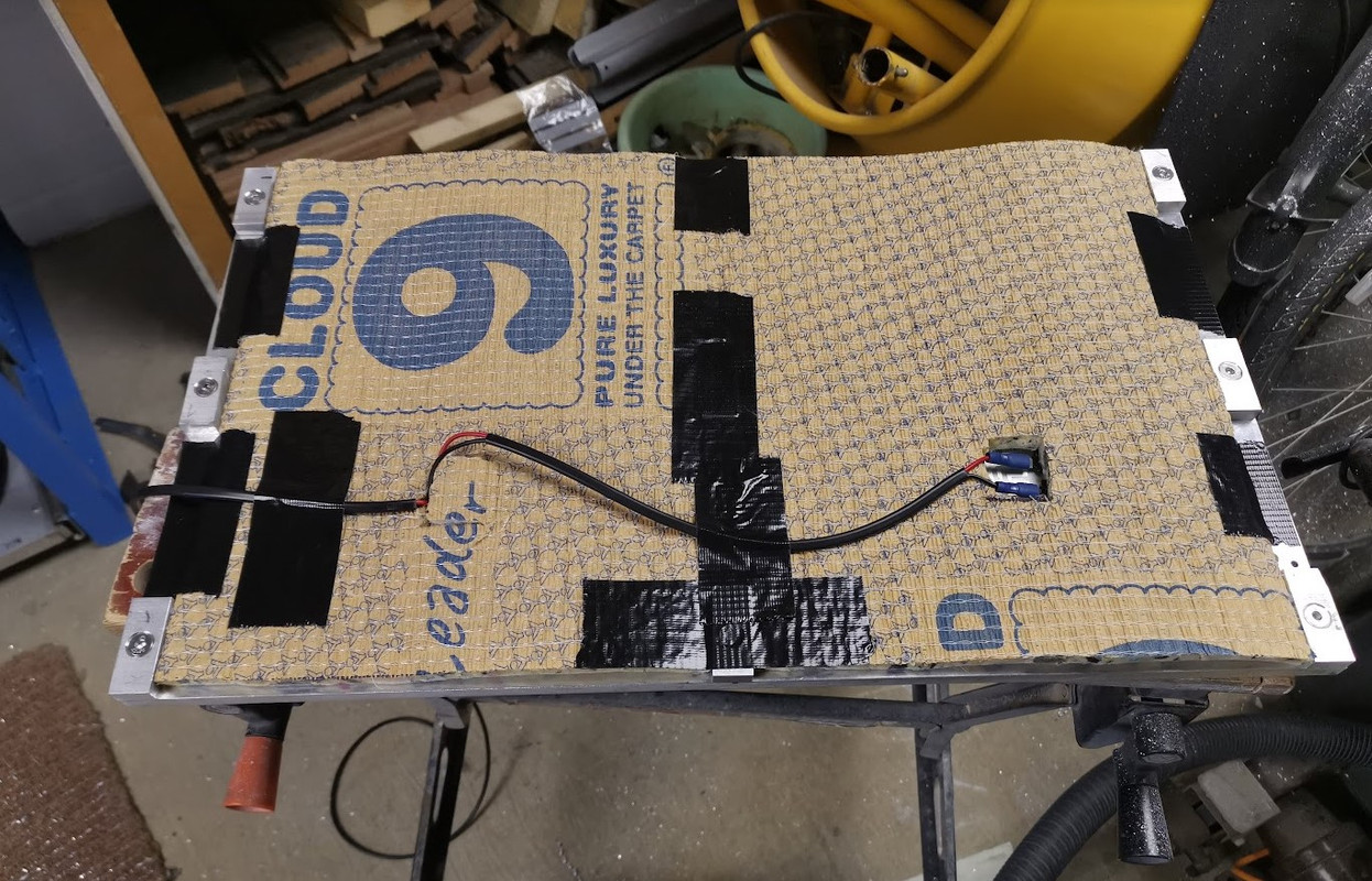
Added a bit of cloud 9 for insulation.
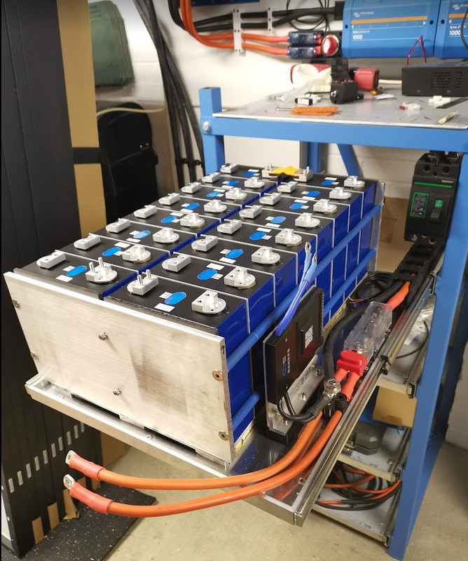
Positive battery connection - once the battery is installed I'll need to make some suitable clamps just to tidy the cables up, otherwise they hit the big breaker when the draw goes in.
The heater pad also has GRP sheet on in for electrical insulation.
BMS mounted
Heater plate - I was going to put a heater pad on the bottom of the tray, but that would heat the entire tray, but I found a bit of 10mm aluminium exactly the correct size, stuck two 24v 40w mirror demister pads on it for heating, and made some feet.
Added a bit of cloud 9 for insulation.
Positive battery connection - once the battery is installed I'll need to make some suitable clamps just to tidy the cables up, otherwise they hit the big breaker when the draw goes in.
The heater pad also has GRP sheet on in for electrical insulation.
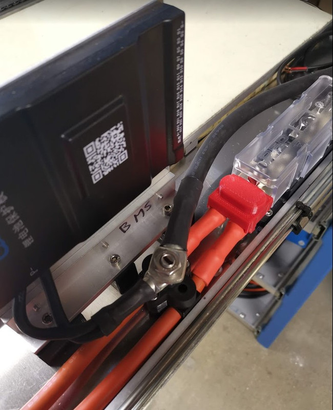
Designed and 3D printed a cover for the cable connection to the battery T class fuse holder.
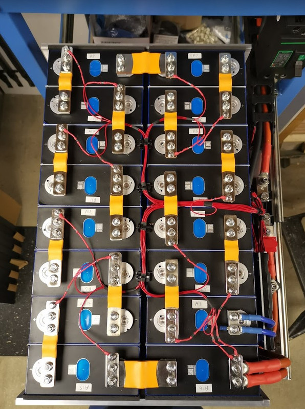
Assembled the pack, will fit the busbars and balance leads tomorrow.
Its a bit scary pulling the battery tray all the way out, the cells weigh 85kg, the aluminium heater tray is 5kg, and there's probably another 5kg in the drawer tray itself.
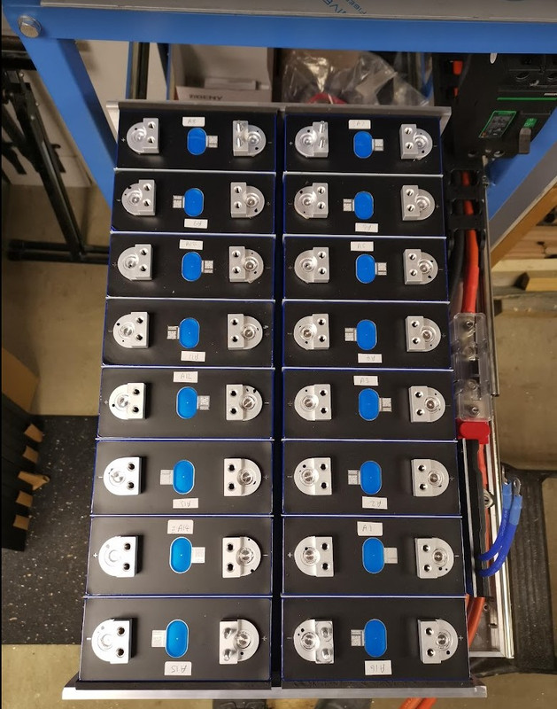
Assembled the pack, will fit the busbars and balance leads tomorrow.
Its a bit scary pulling the battery tray all the way out, the cells weigh 85kg, the aluminium heater tray is 5kg, and there's probably another 5kg in the drawer tray itself.
Last edited:
Soldato
- Joined
- 25 Mar 2004
- Posts
- 15,991
- Location
- Fareham
Should rig it so when you extend the drawer out Metallica - Battery starts playing 
Soldato
- Joined
- 21 Jul 2005
- Posts
- 20,821
- Location
- Officially least sunny location -Ronskistats
Electrician will be doing the AC, connecting the panels and checking my work. LiFePo4 is extremely unlikely to catch fire.
Awesome buddy. Hope they can fit it in soon and we can see the beast running shortly!
Yes, I do, I'll need to find somewhere to mount that.
when you first turn it on it will give you an error code, either 8 or 9, you just need to choose Lifep4 from the menu, and the number of cells to clear the error message.
(the screen connector that plug's into the BMS is a pain to remove, almost impossible if you have the BMS flat mounted to the side of the battery)
I can post up my settings that I have been running on 3 JK BMS battery packs trouble free for months, if it helps?
Last edited:
@Troop, yes that would be a big help, thanks also for the tip about the error code, presume you're using the JK BMS?
The BMS isn't tight against the battery, which will help with plugging/unplugging cables.
The BMS isn't tight against the battery, which will help with plugging/unplugging cables.
@Troop, yes that would be a big help, thanks also for the tip about the error code, presume you're using the JK BMS?
The BMS isn't tight against the battery, which will help with plugging/unplugging cables.
Yes, I have 3 JK BMS's running 3 separate battery packs. (same as you're running but 150A versions)
I'll take screen shots tomorrow morning of my full settings and post them here, be a good quick reference to check against.
Last edited:
@Ron-ski
OK, quick walk through, to change any settings in the advanced menu it will ask you for a Password (default is 123456)
You will be prompted to change it.
Best to work down the list in pairs, changing the lower figure first(on settings that relate to each other), as if you try changing the higher figure to below the lower one it will not accept the figure and revert to the original.
(save after every field change)
Ping me if you're not sure on anything
My settings, same on all 3 battery packs.


My babies")

OK, quick walk through, to change any settings in the advanced menu it will ask you for a Password (default is 123456)
You will be prompted to change it.
Best to work down the list in pairs, changing the lower figure first(on settings that relate to each other), as if you try changing the higher figure to below the lower one it will not accept the figure and revert to the original.
(save after every field change)
Ping me if you're not sure on anything
My settings, same on all 3 battery packs.
My babies
Last edited:
Had to spend some time sorting the boiler out today - condensate pump stopped working, so didn't get as much done as I thought, but I'd forgotten to bring my crimpers home anyway.
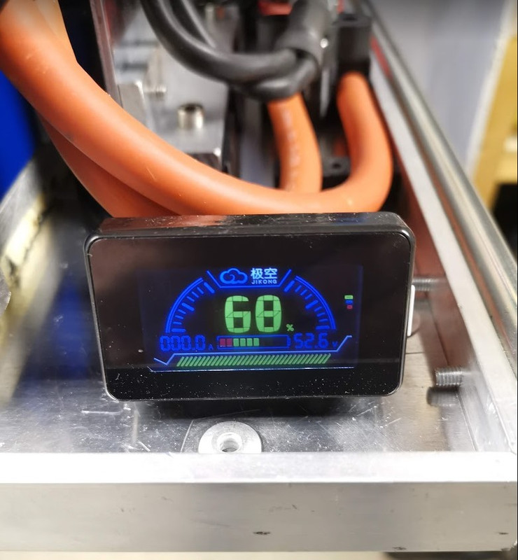
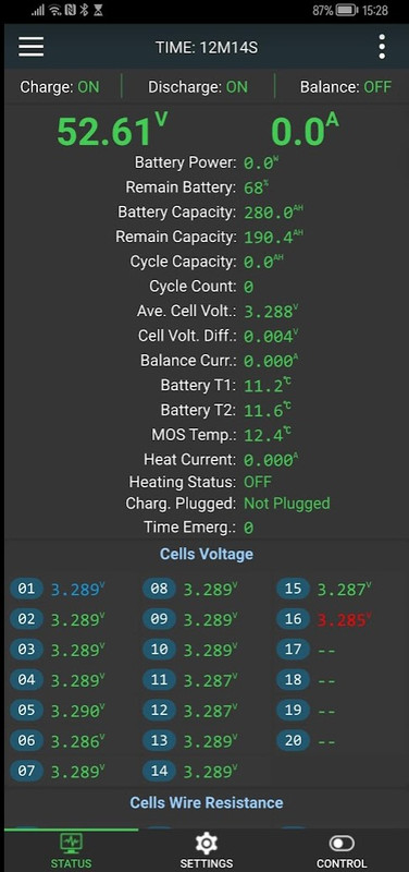
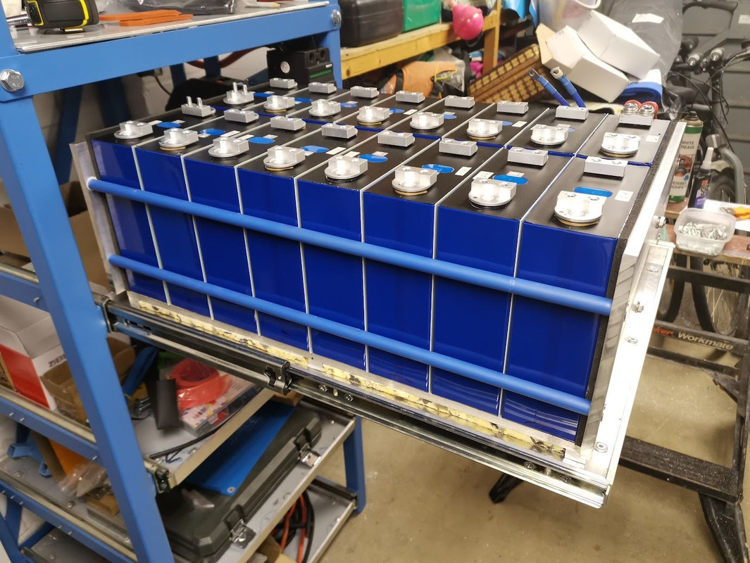
I now have a battery with with circa 52.8v
Still need to connect up the balance leads though.
I now have a battery with with circa 52.8v
Still need to connect up the balance leads though.
Soldato
- Joined
- 25 Mar 2004
- Posts
- 15,991
- Location
- Fareham
Nice Ukrainian colour scheme going on!
Some good news on the Quattro, its now compliant again on the Type Test Register - they moved the goal posts last September, so they all had to meet the new requirements.
Some good news on the Quattro, its now compliant again on the Type Test Register - they moved the goal posts last September, so they all had to meet the new requirements.
Yeah it was updated in the middle of the month, or at least it was last weekend when I checked in order to move forward with my new install over the coming weeks/months.
I hadn't checked for a while, it was approved on the 17th January.
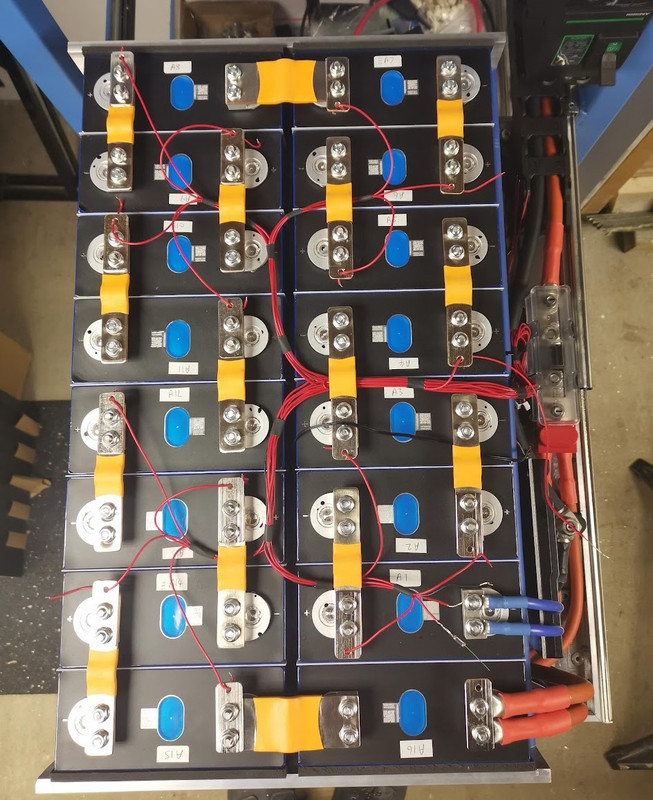
I didn't want to attach the balance leads to the main clamping bolts, I ran through various idea's such as tapping the terminals (M4), tapping the flexi busbars, then I realised I could use the original supplied busbars, so drilled two holes in each busbar, tapped and finally cut them to just under half length.
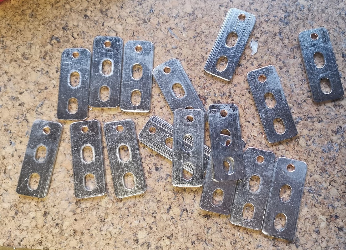
I didn't want to attach the balance leads to the main clamping bolts, I ran through various idea's such as tapping the terminals (M4), tapping the flexi busbars, then I realised I could use the original supplied busbars, so drilled two holes in each busbar, tapped and finally cut them to just under half length.