Ronski's Solar & battery DIY build with whole house backup

Soldato
OP
Joined
3 Dec 2012
Posts
3,642
Location
Kent, much sunnier than Scotland
It certainly does seem to be all the smaller parts, but the prices have risen, as have the prices of metal. Then there's upgrading, so going up an inverter or two sizes which makes sense, but adds a lot of cost, but it will be a very good system that should last a very long time.

And if battery tech changes I'm sure the Victron system could accommodate it so long as it is still 48v.
 
Last edited:
Soldato
OP
Joined
3 Dec 2012
Posts
3,642
Location
Kent, much sunnier than Scotland
Nothing done this weekend, had a new fridge to install, a couple of birthdays to celebrate, and fitted an aluminium print bed that I made to my Sidewinder X1 - currently printing a prototype spacer bracket for the isolator switch.

3-D-Printer-printing.jpg


I need to print spacers for the inverter isolator and the two fuse holders.
 
Last edited:
Soldato
OP
Joined
3 Dec 2012
Posts
3,642
Location
Kent, much sunnier than Scotland
I had a box arrive from America today (Thursday), ordered on Monday - I think that's quicker than most parcels in the UK right now. But then at an excruciating £93 (yes £93) carriage I'd expect it that quick. The contents only cost £37

Box-from-America.jpg


And what is the contents of this parcel you may wonder, well its a sheet of 24" x 24" x 1/4" foam.


Poron-Foam.jpg


This is not just any old foam, it is Poron foam, not quite the type I wanted, but the only one that I could get that will do the job.

Poron foam is like a spring, compress this particular one 25% and it exerts about 13 PSI, as the cells swell the pressure will increase slightly, but won't exceed the maximum of about 18 PSI. During in charging and discharge each cell expands 0.5mm, the much debated consensus is that the cells will have many more cycles when compressed, 1000's more if done properly. Whether this makes a difference depends on how often you cycle the battery, if not many then it may make no difference and age may get to them first.

This is the foam I'm using 86375K234 Resilient Polyurethane Foam Sheet, Soft, 24" x 24" x 1/4" from McMaster

This foam will be used at either end of each pack of 8 cells, the cells will have GRP G10 separator sheets between them, these sheets have been ordered from Spain - cheapest total price I could find.

Made this today.

Isolator-to-fuses.jpg


Drilled a small hole, cut a slit down the bar, then used a chisel and a press to spread the legs out (no sniggering!)

This is what it is for, hopefully it will still make good contact, as there is a little surface distortion at the lower bolt hole, I should have made it a bit longer really.

Oh and the other catch is the studs are so short on the isolator switch that I can only fit the nut and not the spring washer on. I'll use thread lock on the nut, just to be safe.

Isolator-and-fuse-holders.jpg


Currently printing a double fuse spacer for it.

Double-fuse-spacer.jpg
 
Last edited:
Soldato
OP
Joined
3 Dec 2012
Posts
3,642
Location
Kent, much sunnier than Scotland
I'd go the 16Ton version for the longer length handles, makes crimping a bit easier, you still have to use all your strength :)
A lot of crimping to do.

I've been crimping the 70mm inverter cables today, and I wish I had an electric one, never mind a 16t one. The lugs are heavy duty so you can get three crimps on them.

70mm-cable-lug-crimp.jpg


Back box for the isolator and fuse holders fitted.

Fuse-Holders-fitted.jpg


Made an insert for the back of the isolator, there wasn't enough room to fit the spring washers, so I've used thread lock on the nuts, and this insert acts as an insulator between the ends of the copper bar (7mm gap) and locators for the nuts, not that I'd imagine they'd ever come loose.

Back-of-isolator.jpg


I've actually got quite a lot more done than shown here, the four cables to the inverter are made, just need to put the heat shrink on the negative cables, and the inverter isolator and fuse are also fitted.
 
Last edited:
Soldato
OP
Joined
3 Dec 2012
Posts
3,642
Location
Kent, much sunnier than Scotland
When' the electrician due?.

That's the million dollar question, I need to give him a ring on Monday - he's always been a bit slow replying to my updates. Its a bit difficult to judge time wise, but I'm really not that far off now. My last parts for the battery should arrive this week, once that's built its ready for the electrician.

Still need to get my dumb smart meters sorted, its been 14 weeks since I reported it to Octopus, I chased them up last week and they said their metering specialist have said it looks like it’s lost connection with Vodafone for the comms hub, so Octopus have raised a ticket, whatever that means.
 
Soldato
OP
Joined
3 Dec 2012
Posts
3,642
Location
Kent, much sunnier than Scotland
Good productive weekend, although I did find a design flaw, but more on that later.

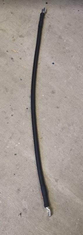
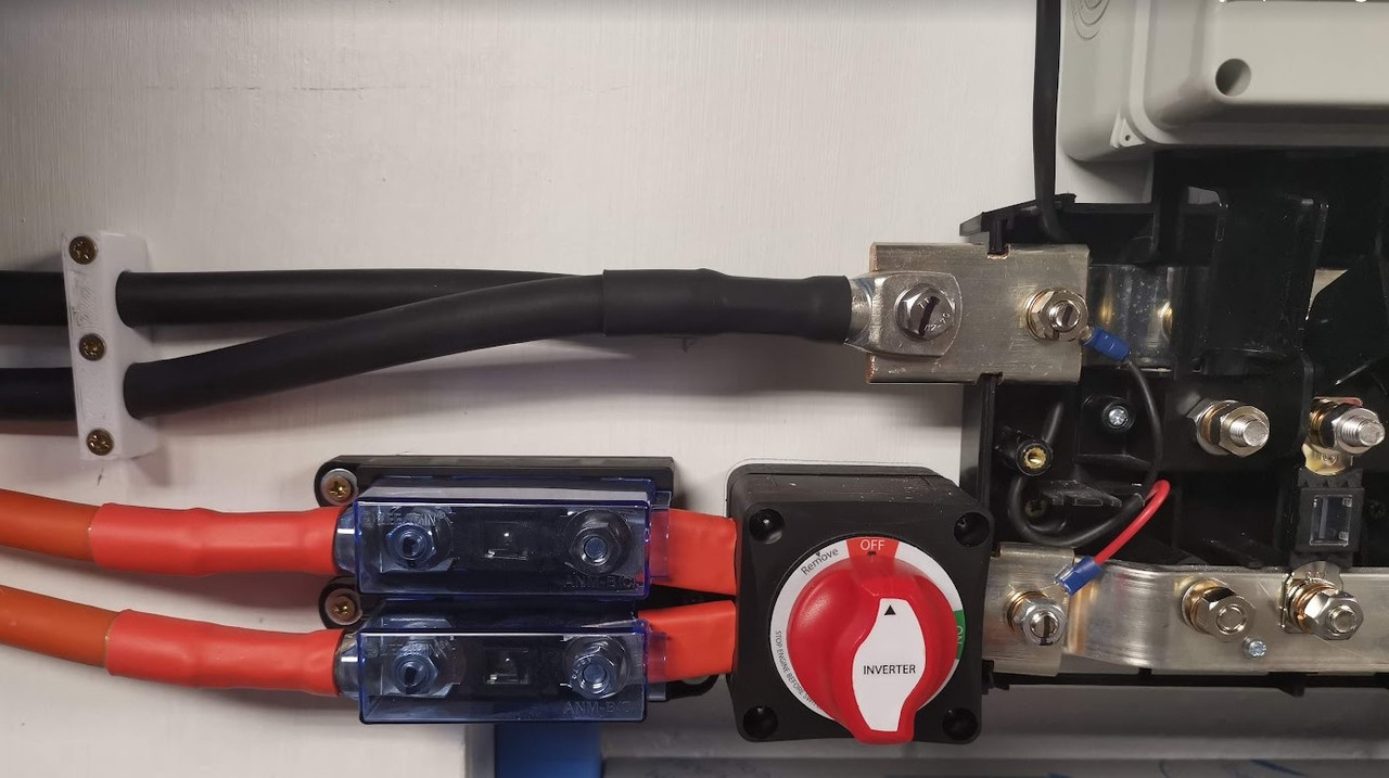
This is one of the two 70mm negative cables to the inverter, I measured the resistance and both were 0.31 milliohms

Inverter-Negative-cable.jpg
Inverter-Negative-cable-close-up.jpg


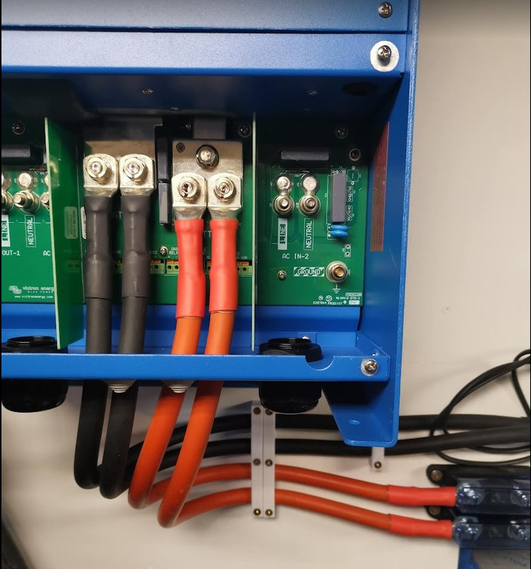
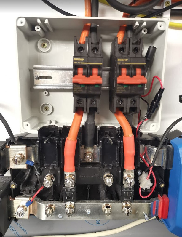
Cables run in to the inverter

Inverter-cables-fitted.jpg


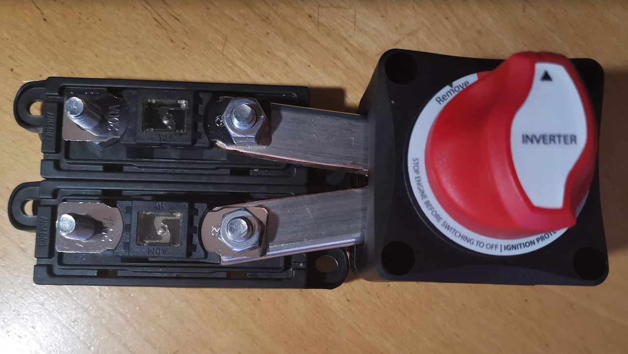
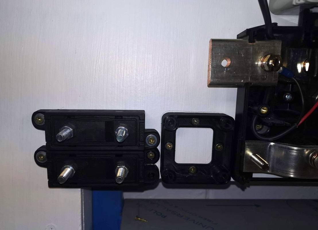
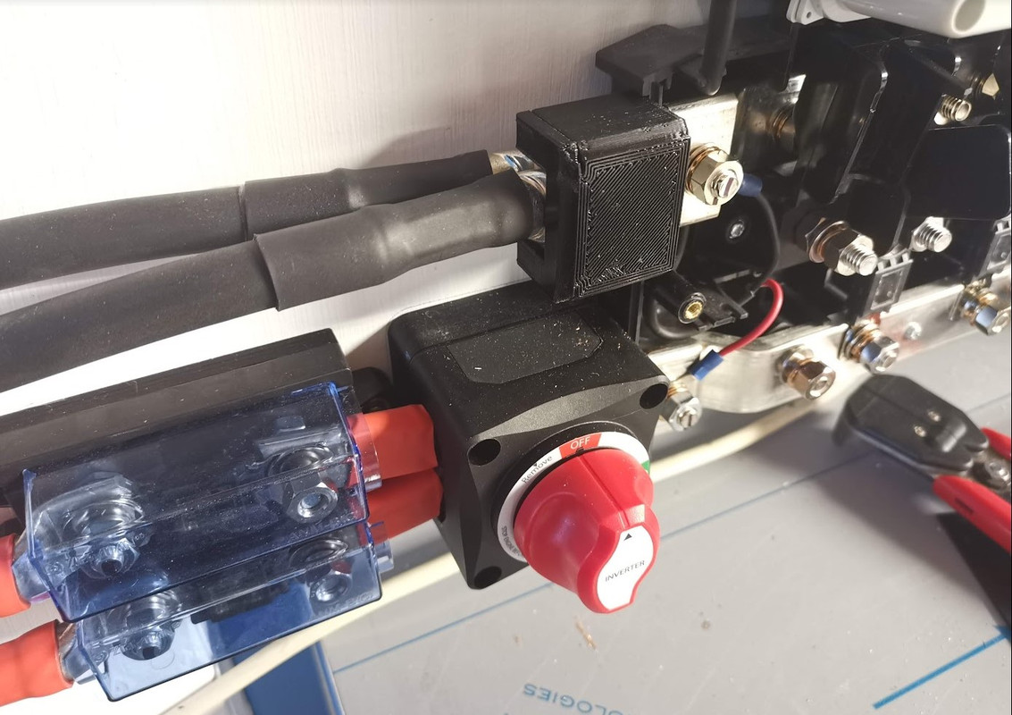
And where they join to the fuses and isolator. The small wire to the right of the isolator needs a fuse adding, this will go to the precharge circuit.

Inverter-Fuses-and-isolator.jpg


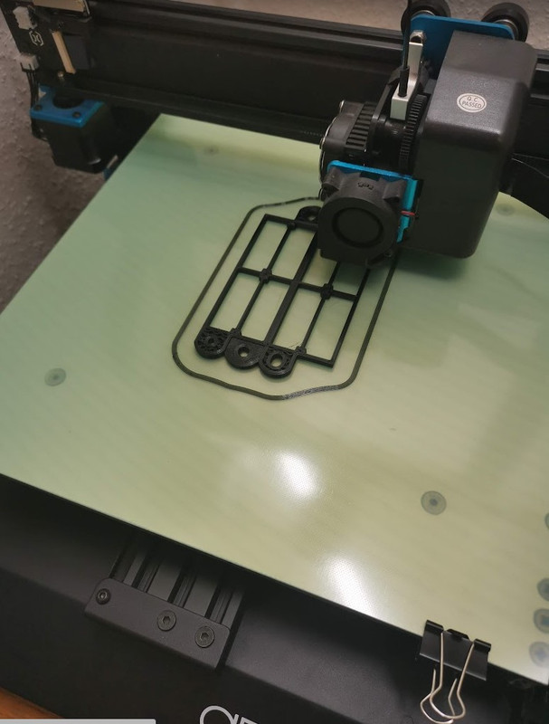
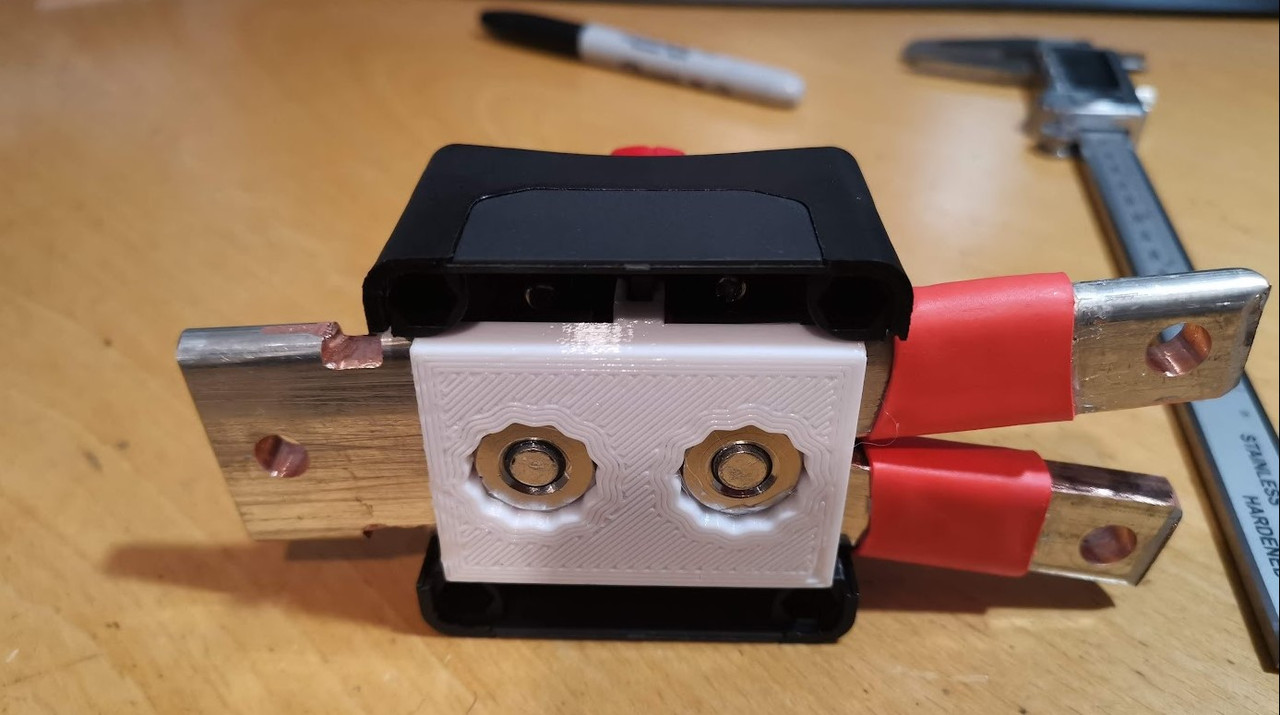
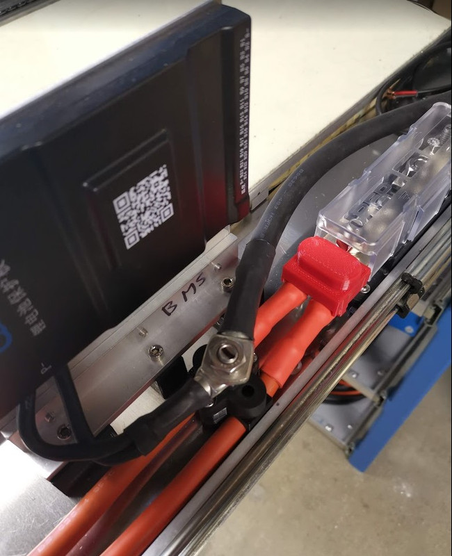
3D printed a clip on cover for the negative connection.

Negative-cable-adapter-cover.jpg


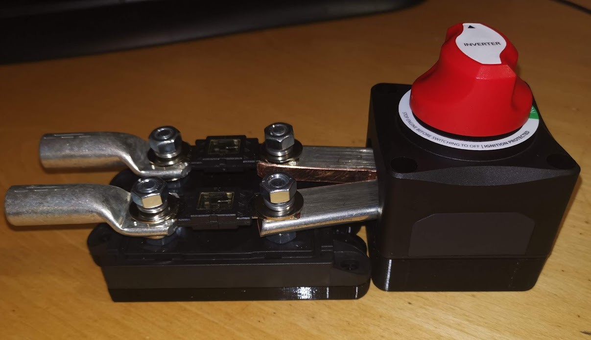
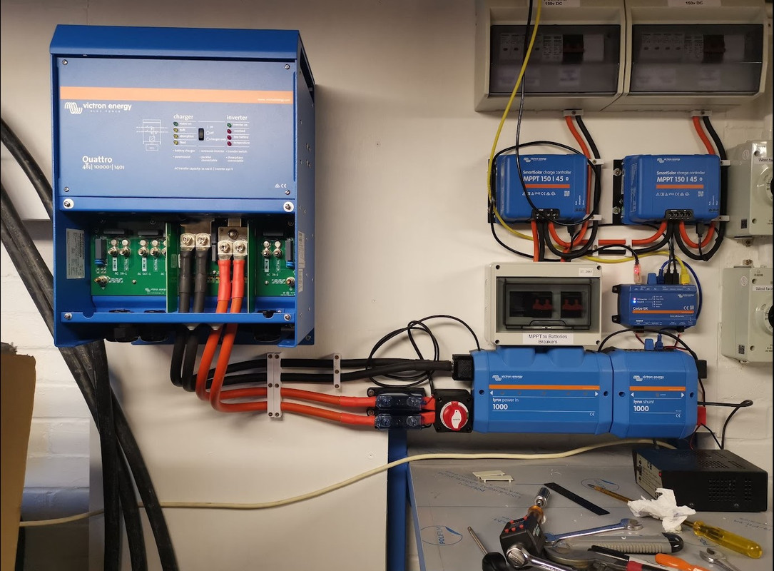
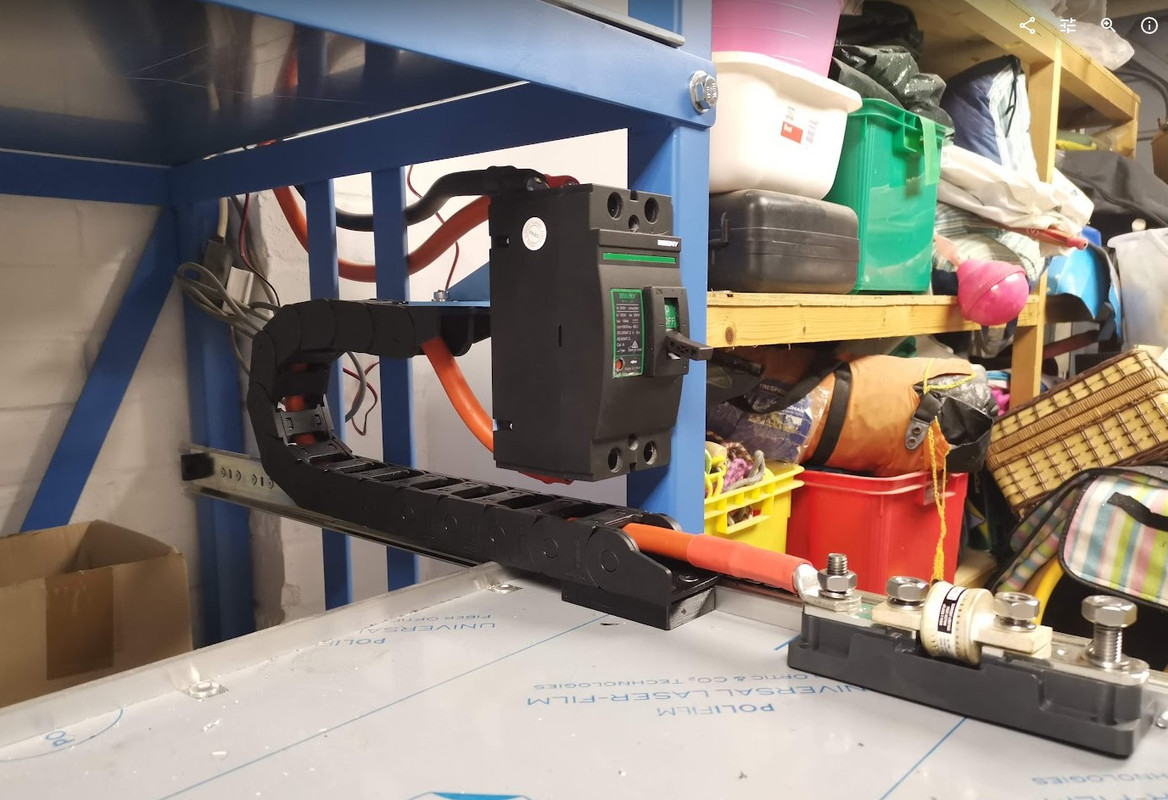
And a bigger overview picture. The small cable coming out the top left of the Lynx Power in will be for the precharge circuit.

System-Overview-1.jpg


Next up was connection for the MPPT MCB's to the Lynx Power in. This was rather tricky as I had decided to use 35mm cable, I could have used 16mm but didn't have any lugs, so 35mm it was, and it was rather tight, just no room, and very short distances, but it fitted.
I cheated on the negative for the left MCB, it should go behind the positive, but it was just too tight, electrically it makes absolutely no difference.

MPPT-MCB-to-Lynx-Power-In.jpg


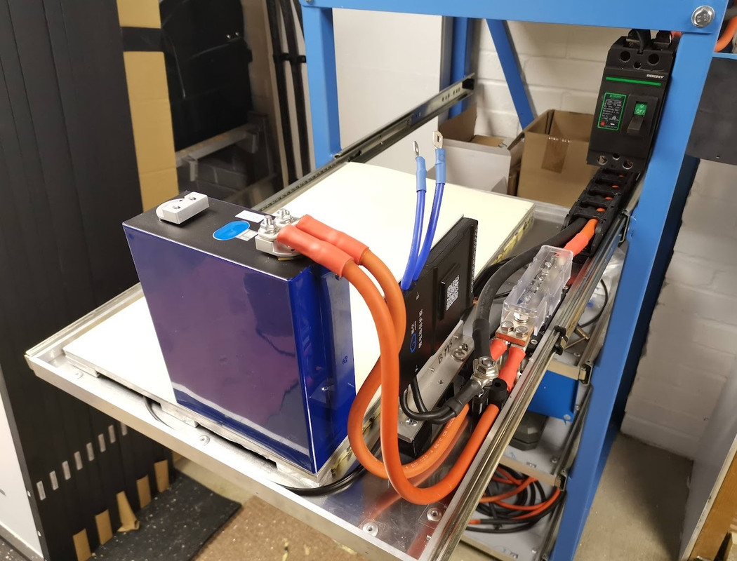
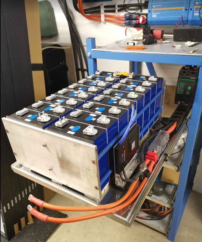
To save on time and as currently I only have one battery, I've fitted the 70mm cables from the top shelf breaker directly to the Lynx Shunt. When I add the second battery, these cables will simply unbolt and connect to the battery rack busbar.

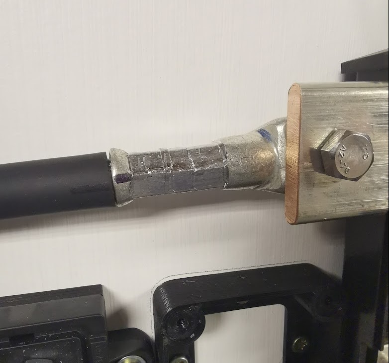
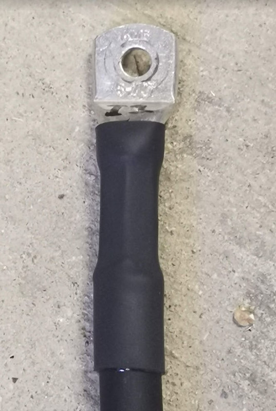
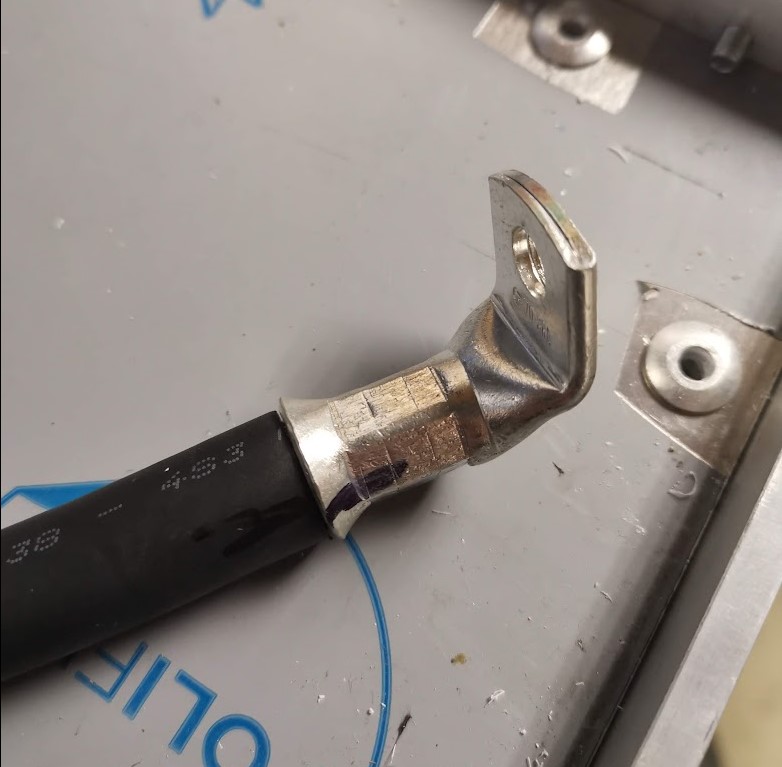
Here's a 90 degree crimp on 70mm cable.

90-degree-crimp.jpg


Positive cable run from the breaker to the T class fuse.

Breaker-to-T-Class-Posistive-cable.jpg


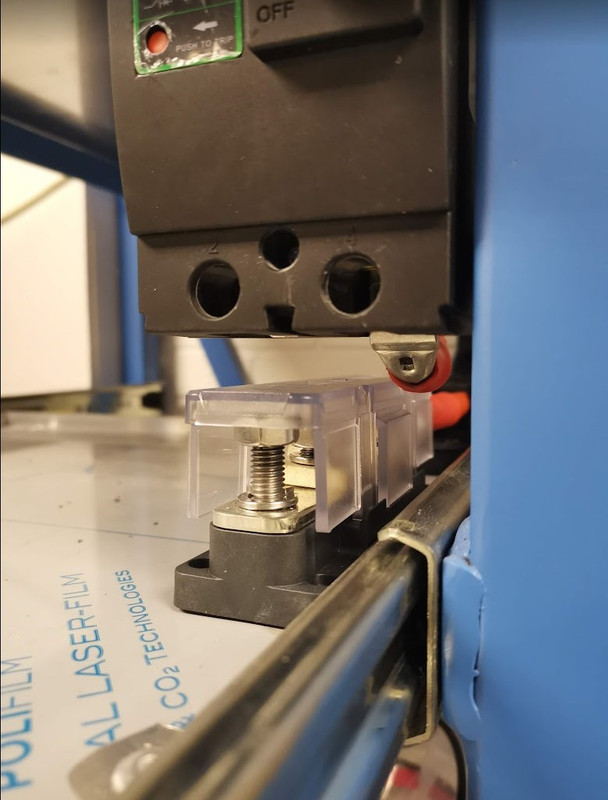
Now this is when I spotted the design flaw, I put the lid on the T class fuse and slid the tray closed, and thought that's a bit of luck it just misses.

But then I realised I still need to connect the negative, and that will not miss!

Negative-will-hit-T-class-fuse-holder.jpg


It's only about 3mm, so I'm going to elongate the mounting holes for the breaker mounting plate, this should allow the breaker to mount about 5mm higher, and then it will clear. Hopefully that works, otherwise I need to alter the brackets, or the riv-nuts in the frame.
 
Last edited:
Soldato
OP
Joined
3 Dec 2012
Posts
3,642
Location
Kent, much sunnier than Scotland
Sorted the clearance problem.

T-class-fuse-holder-clearance.jpg


Pretty awkward to do though, had to drill a total of eight 13mm holes in the back of the box section, then fit M10 riv-nuts with little room to work in. The tool was 500mm long, the gap was only 530mm deep, and not much width given the shelving unit next to it, but its done now.

I will 3D print terminal covers for the breaker, all they supply it with it is a bit of rubber that doesn't fit very well.
 
Last edited:
Soldato
OP
Joined
3 Dec 2012
Posts
3,642
Location
Kent, much sunnier than Scotland
Progress, slow but getting there.

BMS mounted

BMS-and-T-Class-mounted.jpg


Heater plate - I was going to put a heater pad on the bottom of the tray, but that would heat the entire tray, but I found a bit of 10mm aluminium exactly the correct size, stuck two 24v 40w mirror demister pads on it for heating, and made some feet.

Heater-Plate.jpg


Added a bit of cloud 9 for insulation.

Heater-Plate-with-cloud-9.jpg


Positive battery connection - once the battery is installed I'll need to make some suitable clamps just to tidy the cables up, otherwise they hit the big breaker when the draw goes in.

The heater pad also has GRP sheet on in for electrical insulation.

Cabling-done.jpg
 
Soldato
OP
Joined
3 Dec 2012
Posts
3,642
Location
Kent, much sunnier than Scotland
Designed and 3D printed a cover for the cable connection to the battery T class fuse holder.

Battery-Fuse-Cable-Cover.jpg


Assembled the pack, will fit the busbars and balance leads tomorrow.

Its a bit scary pulling the battery tray all the way out, the cells weigh 85kg, the aluminium heater tray is 5kg, and there's probably another 5kg in the drawer tray itself.

Battery-Compressed-1.jpg


Battery-Compressed-2.jpg


Battery-Compressed-3.jpg
 
Last edited:
Soldato
OP
Joined
3 Dec 2012
Posts
3,642
Location
Kent, much sunnier than Scotland
Had to spend some time sorting the boiler out today - condensate pump stopped working, so didn't get as much done as I thought, but I'd forgotten to bring my crimpers home anyway.

I now have a battery with with circa 52.8v :D

Still need to connect up the balance leads though.

Battery-with-Busbars.jpg
 
Soldato
OP
Joined
3 Dec 2012
Posts
3,642
Location
Kent, much sunnier than Scotland
I hadn't checked for a while, it was approved on the 17th January.

I didn't want to attach the balance leads to the main clamping bolts, I ran through various idea's such as tapping the terminals (M4), tapping the flexi busbars, then I realised I could use the original supplied busbars, so drilled two holes in each busbar, tapped and finally cut them to just under half length.

Balance-Bars.jpg
 
Back
Top Bottom