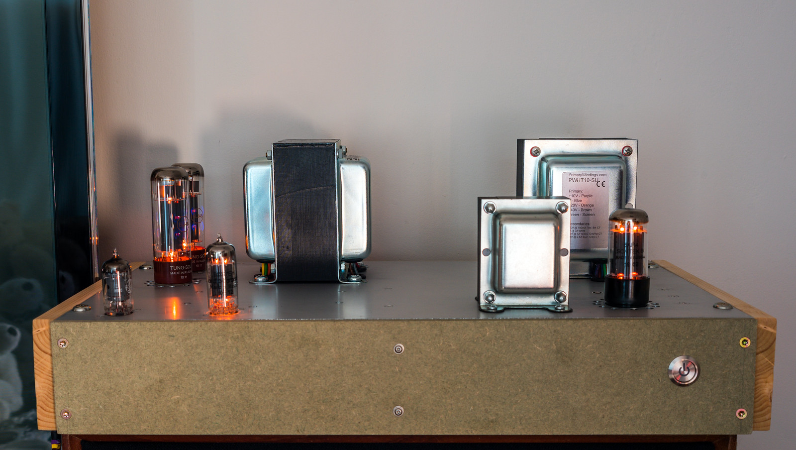
Scratch build valve power amps

What does this mean in practice?

Assuming the same as opamps then the output is used as feedback to control the gain - which usually involves a resistor divider between the output and one of the inputs on the tubes (and ground) and some capacitors for various things including potentially bandwidth limiting so stray noise outside the audio frequencies doesn't upset things, etc.
 
Assuming the same as opamps then the output is used as feedback to control the gain - which usually involves a resistor divider between the output and one of the inputs on the tubes (and ground) and some capacitors for various things including potentially bandwidth limiting so stray noise outside the audio frequencies doesn't upset things, etc.
And to add stability - negative feedback prevents runaway signals by feeding a portion of the output back into the input, out of phase.

In guitar amps it's used to extend the linear portion of the amp's response so it distorts later i.e. more clean headroom.
 
What does this mean in practice?
The main reason to do it is that it cancels out some of the distortion, it helps to flatten out the frequency response at the extremes and it also lowers the output impedance. I've plotted the open loop frequency response at both 1W and 20W on a graph here. (6CG7 rebuild sheet) The frequency response falls off a cliff below 50Hz and above 10KHz. Feedback will flatten this back out to an extent. The low frequency response is affected to a certain extent by the input filtration I've applied to avoid sub sonics causing havoc.

Anyway, closing the loop didn't entirely go to plan as the usual feedback issues returned. However, things were not necessarily as bad as they had been with the previous builds.

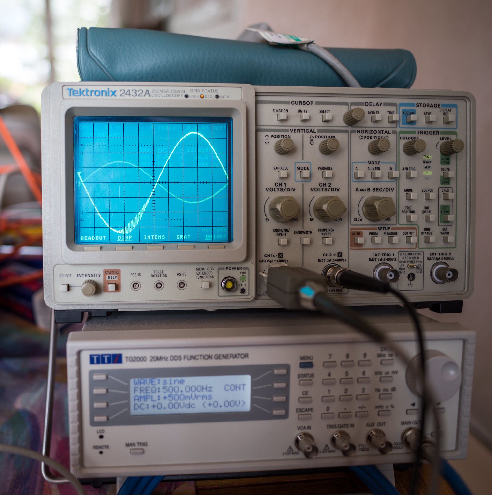
The usual 58ish KHz ringing observed as signal size rises. (shutter speed caught the screen mid refresh hence the dim readout text)
50154371798_8b9c3ad6f2_k.jpg


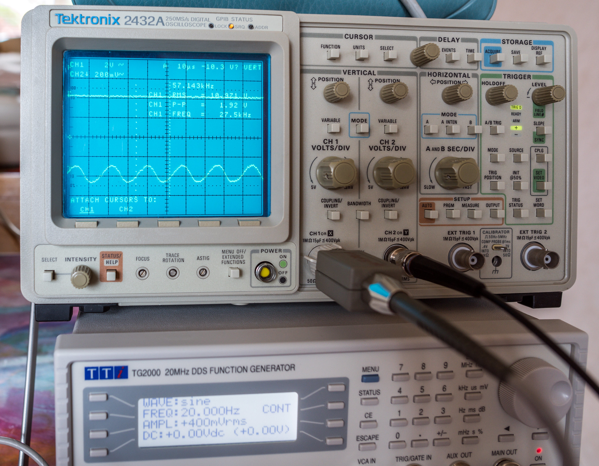
Zoomed in on the oscillation
50155932467_d3053fb52e_k.jpg


Made some tweaks to some component values which made a decent improvement but didn't fix it.
Comparison at 100Hz 500mV input. Left is C11/C12 @ 100nF & R4 @ 10K, right is C11/C12 @ 470nF & R4 @ 22K. C2 was 270pF for both.
50155932072_6f860a9d8d_k.jpg


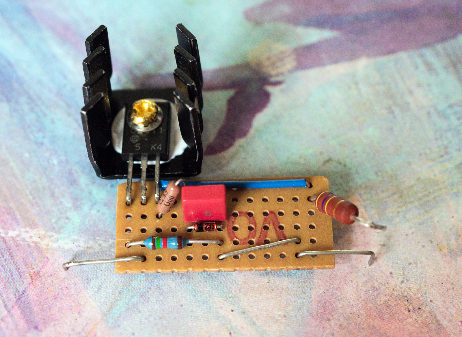
On some suggestions from the DIYaudio folk, I made some further modifications by adding a base stopper resistor on the CCS to make sure that it is unlikely to ever oscillate. A 110R resistor added between the base of the transistor and the capacitor & zener.
50158116458_e9fa4982a5_h.jpg


I also looked at reducing the amount of feedback as it had been suggested that I may have a greater level of feedback than originally planned. This meant increasing R27 from 8.2K. After a quick search through the components on hand, I put in 10K and rechecked. A small improvement but not much difference.
50158667701_67bd22f018_h.jpg


It made sense at this point to look at how much gain there was in the system at each level in order to figure out where things lay.

Open loop gain = 49.54dB
Closed loop gain with R27 @ 8.2K = 27.31dB (22.23dB feedback)
Closed loop gain with R27 @ 10K = 28.75dB (20.79dB feedback)

That explains a lot. The design calls for 17dB of feedback so even with 10K in there, I'm still way past that point. Looks like I need to up R27 to ~18K and try again. Fingers crossed that does the trick.
 
I dug out an 18K resistor and did another test run. It now appears to be stable. With R27 @ 18K I'm seeing 33.26dB gain so about 16.3dB of feedback.

This is how things look now.

100Hz @ circa 11.5Vrms out (matches the previous testing)
50160360457_d9d365c1f6_h.jpg


100Hz @ the limit before it distorts heavily
50159565043_432ae35dda_h.jpg


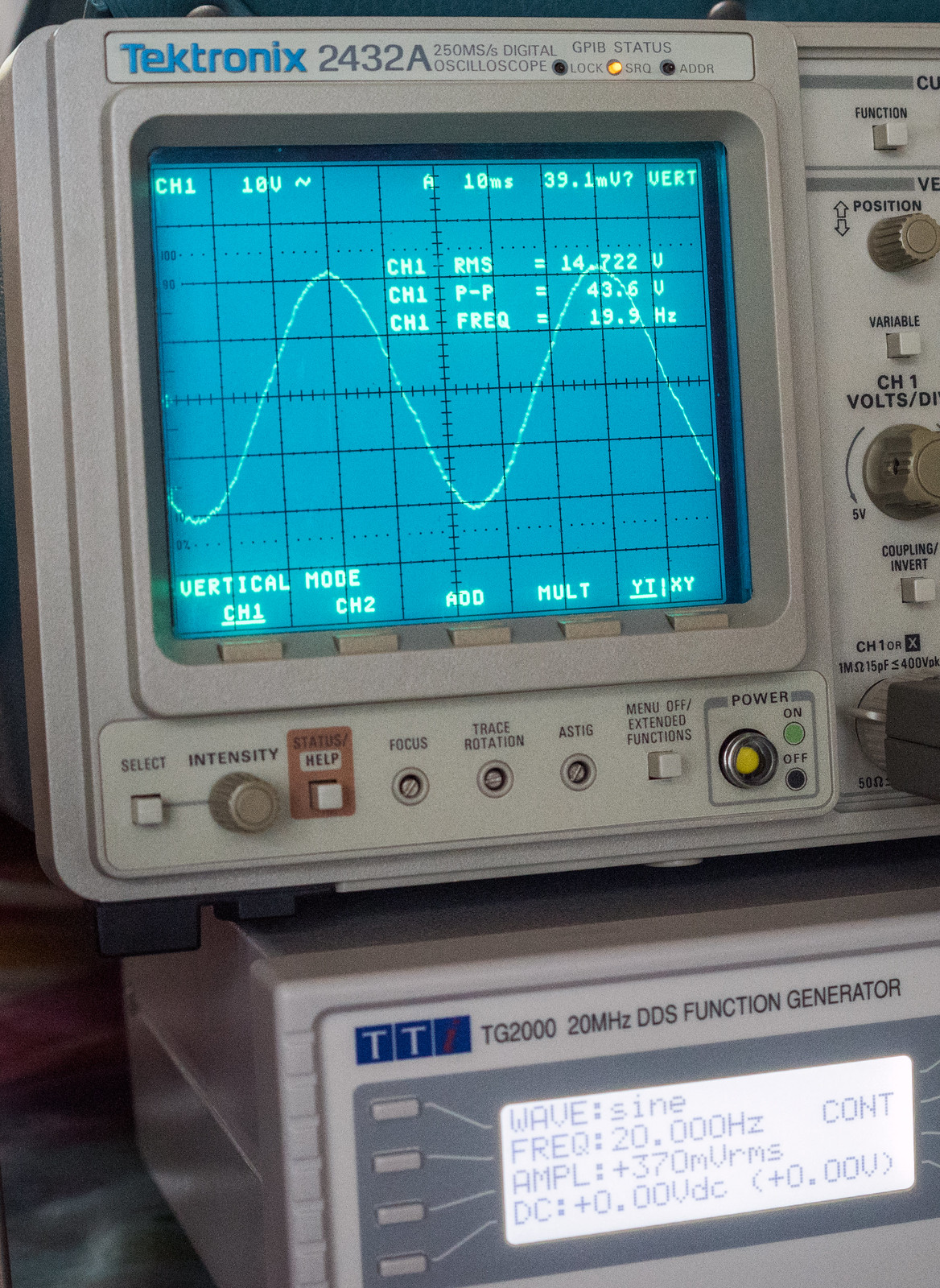
20Hz @ the limit
50160115151_4a61e37273_h.jpg


1KHz square
50160115451_7ee351bd69_h.jpg


10KHz square. The rounding over at the rise and fall appear to be in the input signal if taken after the input veroboard suggesting stray capacitance?
50160115771_a431d5f16d_h.jpg


Schematic as things stand. Also note the voltage at C2 and L1 are quite a bit higher than the model. May explain the additional power before clipping starts.
50159577478_5adbe731dc_h.jpg


Overall, I'm extremely pleased as I've had hell getting this thing stable. The output transformers could be a bit better which would likely have net a small improvement in HF response and probably made the feedback loop a bit easier to stabilise.

Major trial by fire, I have run it all day on the other set of valves. It has passed with flying colours and sounds great. Now I need to build the other one. Ideally though, I need to build it all on a smaller chassis as this one is a bit big.
50163013981_df26e1dbe1_h.jpg
 
Last edited:
Some way to go then for a 5.1 system!
Lol, that would be some cost not to mention the heat output. Just the one monobloc generates quite a lot of heat.

As for 5.1, I've got three stereo solid state amps that currently fulfil that role.
16355504660_c74a33c237_h.jpg


Anyway, in other news, I've tested all of the valves I have on hand and have found that the new Tung-Sol EF806SG appears to be duff as it causes excess hiss and simply doesn't sound right, but the older GE 6267's work fantastically. (6267 is just the american numbering for an EF86, EF806S is a lower noise construction EF86) I can't easily distinguish between the jj KT77's and the EL34B's. I guess we'll see which last longest. I may get a set of EH 6CA7's just to complete the array of choice I have for this pentode/beam tetrode family. I will say that in a looks contest, the EL34's win because who doesn't love a good bit of blue glow. No sign of red plating either.
 
Last edited:
How long should valve amps last?
Only experience I have with that sort of thing are nixie tubes. And some of those have had quite a short lifespan. But I suppose these valves wont be on for long hours, just occasional use, unlike the tubes I've used.
 
How long should valve amps last?
Only experience I have with that sort of thing are nixie tubes. And some of those have had quite a short lifespan. But I suppose these valves wont be on for long hours, just occasional use, unlike the tubes I've used.
The lifespan depends entirely on the construction quality of the valve and how they are used. In the early stages of my design saw the valves showing signs of excessive dissipation with parts of the anode structure starting to glow. (Known as red plating) This exponentially shortens the life if left to run. If limits are respected and the idle bias is set conservatively, they should last a few thousand hours. The little noval valves in the voltage amp/phase splitter stage see such low currents that they should easily last many thousands of hours. (10000 hours is not unknown)

Do you have your own power station to run that lot?
Thankfully I almost never run it all at the same time.
 
Last edited:
Excellent stuff. Sorry if it's been answered, but do you have a cost for all of the components required, ie total cost to build?

I'm an ex electronics engineer that used to fix HF and VHF radios. So it's great to refresh my memory reading this thread. I say ex, I think the last time I touched a signal generator or an oscilloscope was around 2005!
The BOM

It's not as up to date as it should be as I stopped updating it amid the chaos of a double rebuild mid way through. The cost should be approximately correct for the bulk of the components, though some parts are missing as I used parts I already had. The one big thing missing from it is a chassis as I'm yet to buy anything. I've built all these prototypes on what I had in storage. I'd estimate about £1500 in total for a pair.
 
Finished the graph for frequency against dB. As I had also plotted results for the earlier Claus Byrith version (I called it Elektor in the data), that can also be seen on there, both open and closed loop. For those that want to see the numbers and formulae, here is the link to the sheet.
50181157131_53db33f4a8_k.jpg


The rise in the sub 10Hz response on the blue plot is the instability with feedback on the Mk2 build. The current build is yellow for closed loop (feedback connected) and green for open loop. (feedback disconnected) It shows quite clearly the flattening of the gain of the amp once feedback is introduced. One thing this graph doesn't show is distortion as I currently have no easy way to measure it. The red to green improvement in the HF response from moving away from a 12AX7 phase splitter is pretty big. One thing the graph cannot show is the distortion. The 12AX7 would start to show distortion above 10KHz long before hitting 20W output. I'll see if I can measure it at some point using a free tool called soundcard scope. Need to buy the breakout cable for my RME interface card.
 
Last edited:
For those that don't have a proper valve power amp, it's definitely not something you would want to run in the summer without good ventilation or air conditioning. It'll make a very good heater in the winter though. This is the approximate glass bulb temperature on the output valves.
 
Fitted the Electro-Harmonix 6CA7's today and am giving it a test. I think it may be my imagination but it definitely seems to sound a bit better. I think there may be more gain or something, but either way, they sound really good.

They also look good too as they have a slightly broader bottle and a bigger plate structure.


Power valves side by side. Even though all 3 are rated virtually identically, I'd be surprised if the 6CA7 couldn't dissipate more power simply due to the size and fining of the plates.
 
Last edited:
For those that don't have a proper valve power amp, it's definitely not something you would want to run in the summer without good ventilation or air conditioning. It'll make a very good heater in the winter though. This is the approximate glass bulb temperature on the output valves.

Ultimately it will depend on how much heat (wattage) is being generated - with my headphone amps (solid-state) worst case you are still sub 3 watts IIRC.
 
Ultimately it will depend on how much heat (wattage) is being generated - with my headphone amps (solid-state) worst case you are still sub 3 watts IIRC.
I'm not 100% sure on the exact dissipation on this but the norm for a cathode bias amp is ~90% which makes it very close to class A with each power valve dissipating nearly 25W. This is simply because the bias shifts about during operation because of the current limiting from the resistors. Lowering the bias by increasing the resistor size reduces the available power output.

The zener diodes I put in series with the biasing resistors allow for reduced bias without power loss but makes the amp less tolerant to valve imbalance and run away.

Another very big factor to take into consideration with valves is the heaters. The rectifier alone has a 15W heater(5V @ 3A). Then there is 9.5W per output valve (6.3V @ 1.5A) and around 1.5-3W for the little valves. (6.3V @ 0.3 & 0.6A)
 
Last edited:
Back
Top Bottom