Scratch build valve power amps

Man of Honour
Joined
13 Oct 2006
Posts
91,058
CCS in this case meaning constant current source. The transistor is nothing special (2SC2611), CCS describes its purpose in this particular application. It's used in the cathodes of the phase splitter which sets the bias, due to its active nature, it also helps to balance both triodes in the valve. (so the push and pull halves are equal) The more traditional way of doing this is with a resistor but that is susceptible to drift as the voltage changes.

Not tried with a valve amp but never found I was happy with just a resistor for biasing in audio applications. Obviously not applicable to what you are doing but in my experience with modern opamps you generally don't gain anything from output biasing despite some people jumping up and down about class A, etc. (some exceptions aside).
 
Soldato
Joined
27 Feb 2004
Posts
2,537
Location
Kent
"Finally got the MK3 prototype finished. Should be able to do some testing once I've triple checked my wiring. Everything looks good so far."

Does it work??
 

Kei

Kei

Soldato
OP
Joined
24 Oct 2008
Posts
2,750
Location
South Wales
"Finally got the MK3 prototype finished. Should be able to do some testing once I've triple checked my wiring. Everything looks good so far."

Does it work??
I've still not got as far as testing it yet. I double checked my wiring and found a missing ground connection. I'm also double checking the component values for the biasing as I really don't want to muck that up and end up cremating a set of valves.
 

Kei

Kei

Soldato
OP
Joined
24 Oct 2008
Posts
2,750
Location
South Wales
Got around to a test run today. No dramas thankfully, however there is clearly something not right as the phase splitter is not behaving correctly. The anode of EF86 looks great but the output of 6CG7 looks awful and notably, the anode voltage on 6CG7 is way over where it should be.

This is the schematic exactly as built. Blue voltages are the simulated values from LT spice. Red are what I have measured.
50123579927_f1898eed9a_h.jpg
 

Kei

Kei

Soldato
OP
Joined
24 Oct 2008
Posts
2,750
Location
South Wales
Having just re-checked my drawing of the CCS board and the datasheet for 2SC2611, it appears that I have successfully mirrored the transistor connections. I've connected the base and emitter backwards which would explain quite a lot. It was wrong in my drawing which is why when I checked it, I missed the error.
 

Kei

Kei

Soldato
OP
Joined
24 Oct 2008
Posts
2,750
Location
South Wales
Took the transistor out and checked it. It tested ok so I put it back in the correct way around and reran the test with no feedback. Voltages seem to be a fair bit better, possibly a bit low if anything, which I can correct by moving the primary over to 240V instead of 250V.
50124872423_e2a518508d_k.jpg


Some slight oddities I noticed:
- The measured voltage at the anodes of 6CG7 differ by 3V
- ~100mV of noise on the anodes of 6CG7 at idle
- EF86 clips on the positive half of the waveform @ ~70mV which throws the balance

This is an example of what I mean by the limited output power. It's clean at 60mV input across the whole frequency range.
50125445246_4e83b7f65c_k.jpg


It starts to distort around 80mV and by 100mV input it's well gone.
50125445106_5c546b8a12_k.jpg
 
Soldato
Joined
27 Feb 2004
Posts
2,537
Location
Kent
Nice bit of test kit! I think that you are operating beyond the knowledge of most of us - I tend to build any amps etc from modules designed by others . . ..
 
Man of Honour
Joined
13 Oct 2006
Posts
91,058
Yeah nice bit of kit - my oscilloscope is a fairly cheap USB one with most of the functions in software - beyond some simple tests for things like ringing much of it is beyond my working knowledge.
 

Kei

Kei

Soldato
OP
Joined
24 Oct 2008
Posts
2,750
Location
South Wales
The scopes are really getting on a bit now but still more than up to the task. It would be very nice to have a modern slimline, quiet scope with a colour screen to make differentiating between channels easier.

Doing some further testing this morning using a 6267 instead of the EF806S and saw much better results. (102V on the plate) What was not so good is I also noticed that half of the HT winding was only showing 10Vac and the other half 390Vac.

Checking the mains transformer winding resistance across both halves shows it as open circuit vs my other one which shows 168ohms. It's spec is 410-0-410 @ 180mA which I would have thought is sufficient for this design. I think it'll have to go back to primary windings.
 
Soldato
Joined
27 Feb 2004
Posts
2,537
Location
Kent
Presumably D1, D2, R24, R25, F2 and F1 all "as expected" ? If only half of tx giving volts would you get a very unsmoothed DC out of V3?
 

Kei

Kei

Soldato
OP
Joined
24 Oct 2008
Posts
2,750
Location
South Wales
Presumably D1, D2, R24, R25, F2 and F1 all "as expected" ? If only half of tx giving volts would you get a very unsmoothed DC out of V3?
Yep all as expected. Essentially, the amp has been running with half wave rectification. The one half of the HT winding is definitely gone, I'm just not sure why. The HT winding is supposed to be overspecced as the amp as standard is supposed to be ~145mA draw with the option of 40mA for a pre-amplifier/radio receiver. 6CG7 has a greater draw than the original 12AXX&/ECC83 but it should easily be within the comfortable limits of the rating on the transformer.
 

Kei

Kei

Soldato
OP
Joined
24 Oct 2008
Posts
2,750
Location
South Wales
I'm now wearing my "disappointed at myself face" and the dunce hat.

I took the transformer out today in order to pack it to ship back and thought I'll test it again. The "dodgy" side now showed about 1Meg resistance to centre tap which I thought was a little odd as it was totally open circuit yesterday and wiggling the cables showed no difference. Removed the crimp and tested after stripping back some insulation and it all measures good now.

I'm having a rethink on the crimps. I checked the wire and can't see a size printed on what is there as, typically, the wire length is too short to have all the text there and each of the 4 HT leads is missing that bit of text. I'd assumed based on the fact that the other wiring was 18 AWG and 20 AWG that this slightly slimmer stuff was 22 AWG. These red (more like pink) crimps I've got are for 16-22 AWG. I would solder the connections but I feel the plastic body of the fuse holders isn't particularly heat resistant. Do I splice in some thicker cable and crimp that or do I buy 22-26 AWG crimps?
 
Man of Honour
Joined
13 Oct 2006
Posts
91,058
Though I agree with your concerns - I would solder it if you can. I've had no end of issues related to poor connections when building amps when using crimps, etc. (though a lot of that was due to wear while swapping stuff in and out for A B testing, etc.).
 

Kei

Kei

Soldato
OP
Joined
24 Oct 2008
Posts
2,750
Location
South Wales
All reconnected now with solder and sleeving. Voltages are now much higher after the rectifier. I think I still need to tweak the resistors around EF86 to get the operating point closer but it's not too far out.
50141734492_4b2da19bbd_k.jpg


It's performance doesn't look too bad without feedback. Certainly better than the 12AX7 phase splitter. It still gets quite out of shape around 11Vrms output, particularly on the negative cycle. I'm guessing that the V1/V2 operating point is still playing it's part in that. There's also the obvious signs of crossover distortion too.
50140953958_968cc426a8_k.jpg


Even a 10K square wave doesn't look bad. The frequency response is remarkably flat at lower power outputs. Towards that 11Vac output, the response starts to fall slowly from 14KHz.
50140954453_967c26dfba_k.jpg
 

Kei

Kei

Soldato
OP
Joined
24 Oct 2008
Posts
2,750
Location
South Wales
Interesting to read / watch as the story unfolds! Those voltages look SCARY.
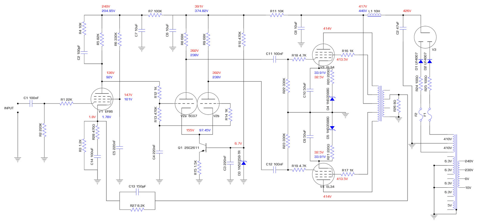
I've seen over 500V a few times. The one time I tested it without the output valves in place I saw well past 500V. It's still very small in comparison to the EHT in old television set cathode ray tubes. IMO, my F&T 47uF capacitor which is only rated at 500V is probably going to need to be replaced as I'm seeing a brief peak of 510V at switch on which isn't going to help it's lifespan.

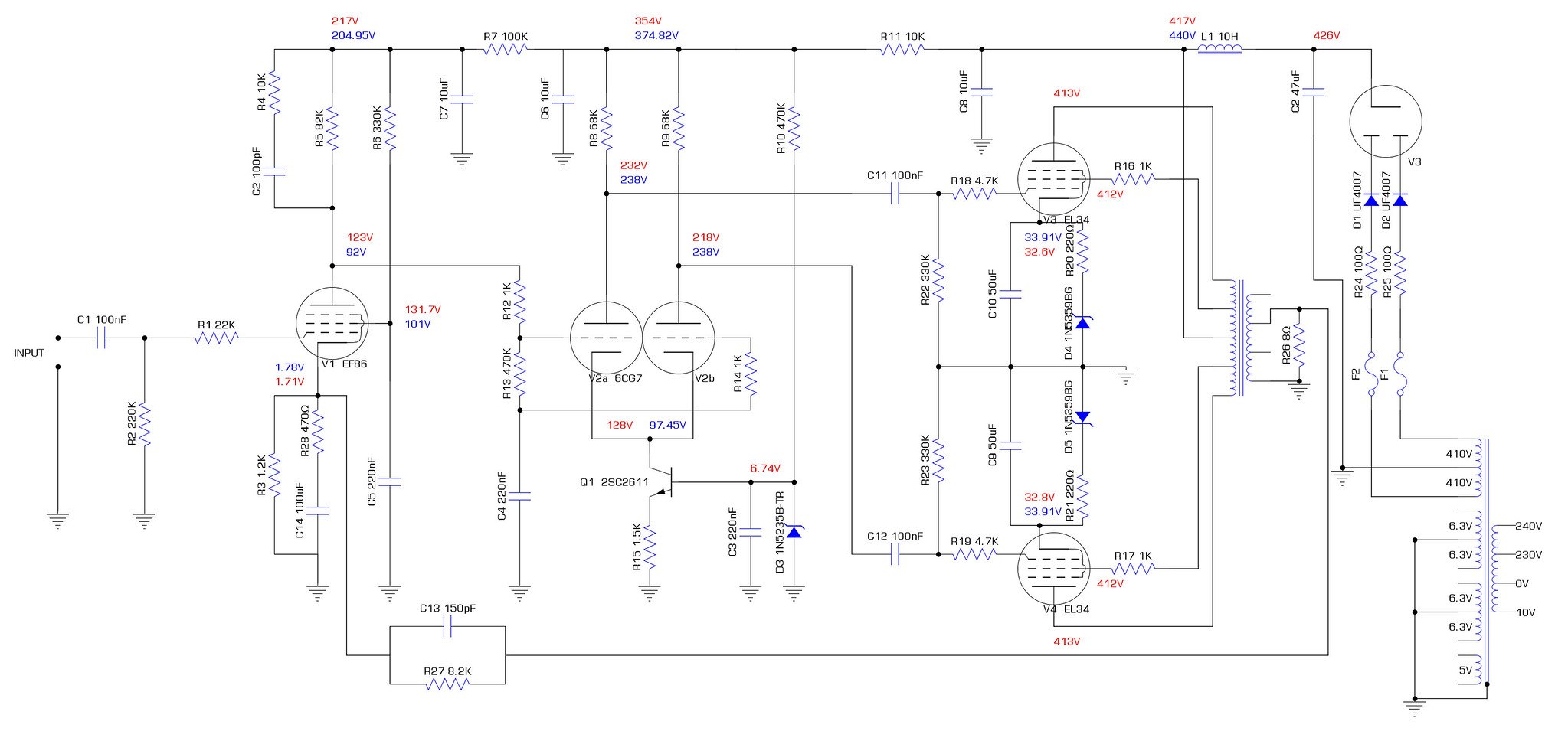
I made some adjustments to the cathode on EF86 and ran some tests. First thing I tried was removing the 100uF cap and 470R resistor leaving only the 1.2K resistor in place. Zero effect observed, voltages remained the same. I then swapped out the 1.2K resistor for a 1K. I also swapped out the JJ GZ34/KT77's for EL34B/5AR4. The JJ GZ34 clearly has more sag than the sovtek 5AR4 as the voltages out of it were ~10V higher. The behaviour of both V1 & V2 seemed to be far better with the voltages being much closer to expected. I also noticed the asymmetric distortion on the output has now gone, only showing slight signs of crossover distortion as the output passes 13Vrms. (21W into 8 ohms)

This is how things were with just the cathode of EF86 changed.


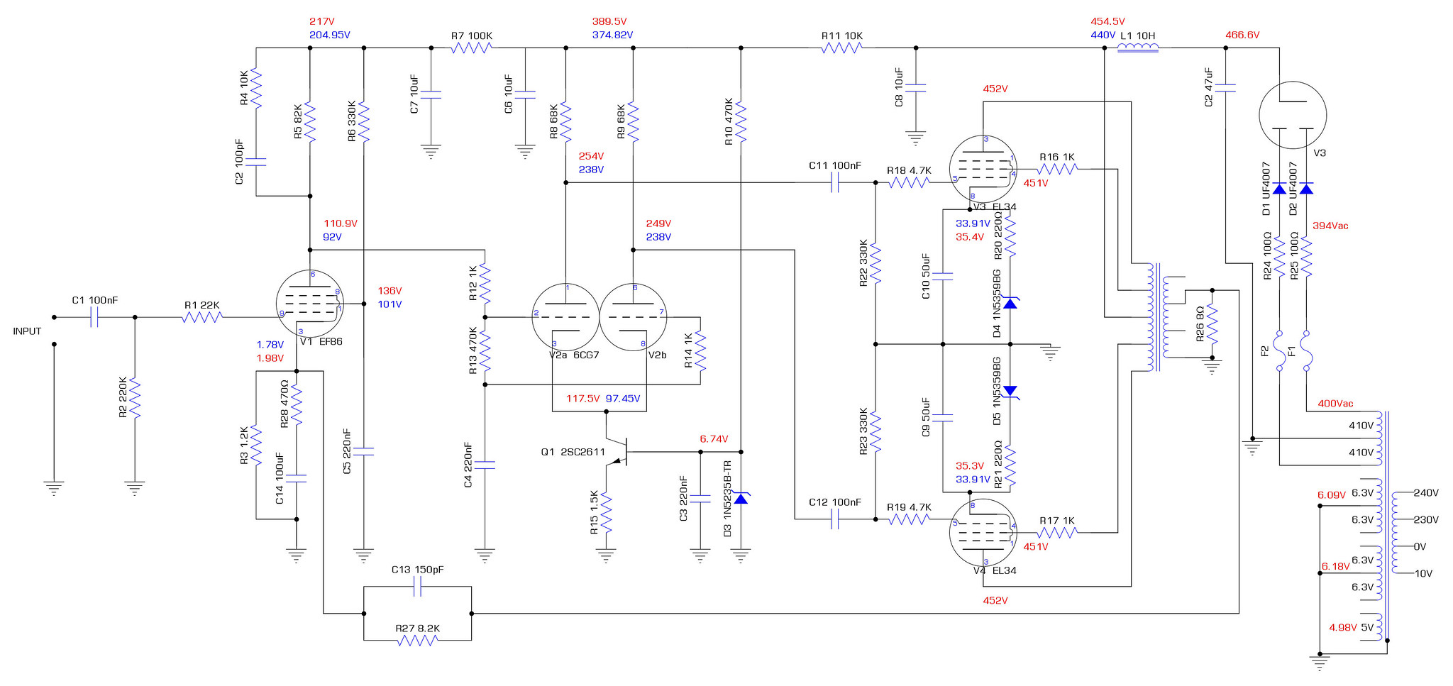
Changed the R6 screen grid resistor to 470K as I wanted to actually see the effect on the voltages across both V1 & V2. I was surprised at how big a difference it actually made everywhere else, yet the screen voltage change was pretty small.

V1 Anode increased by 26V, G2 decreased by 8V and the cathode decreased by 0.15V. V2 anodes remained the same but the cathode increased by 11V.

Anyway, I put the 330K back in as that seemed to produce voltages in line with expectations considering the higher supply voltages. I can't remember where I read it but it said about the screen being a 1:4 ratio with the anode, so 82K*4=328K.

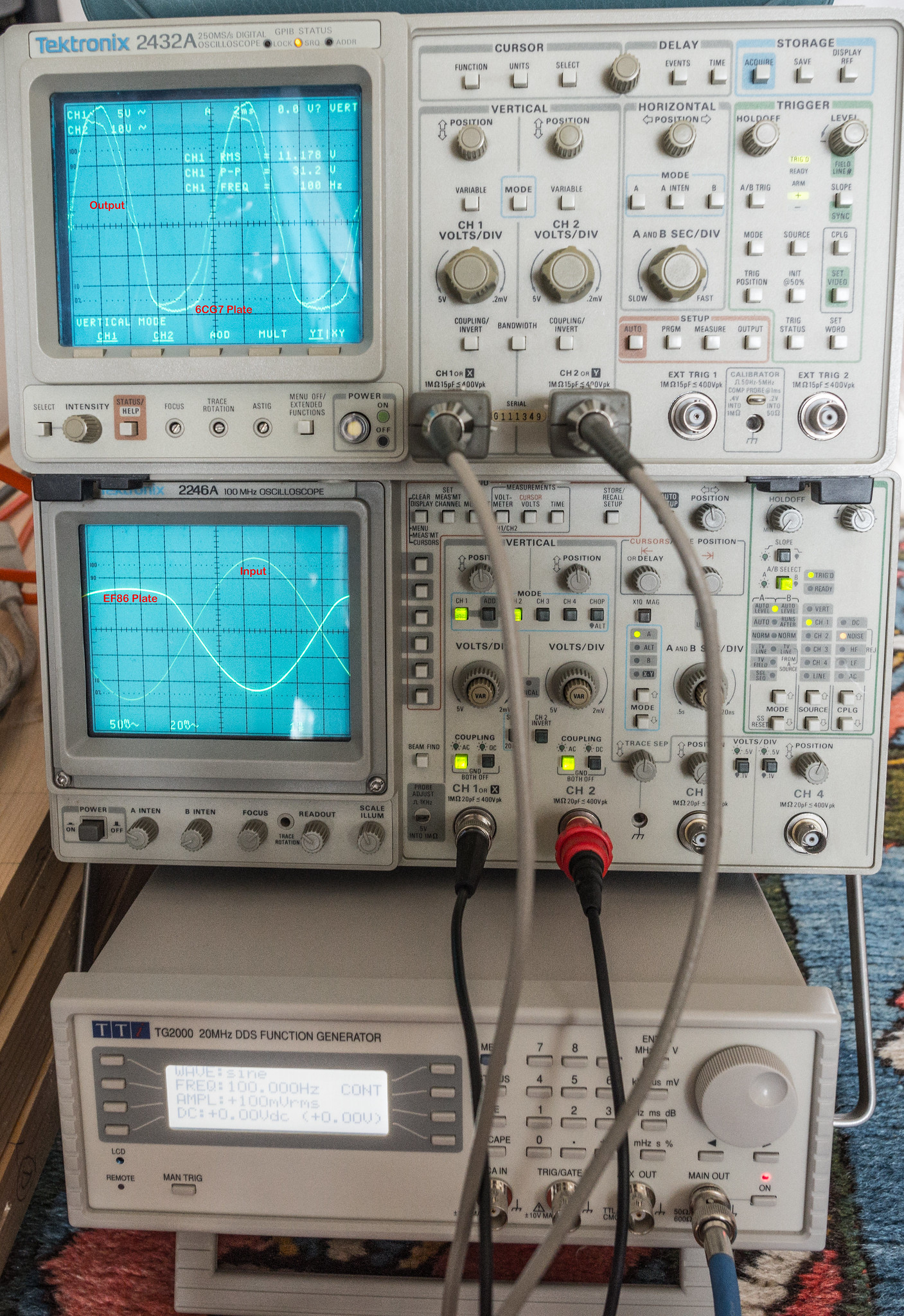
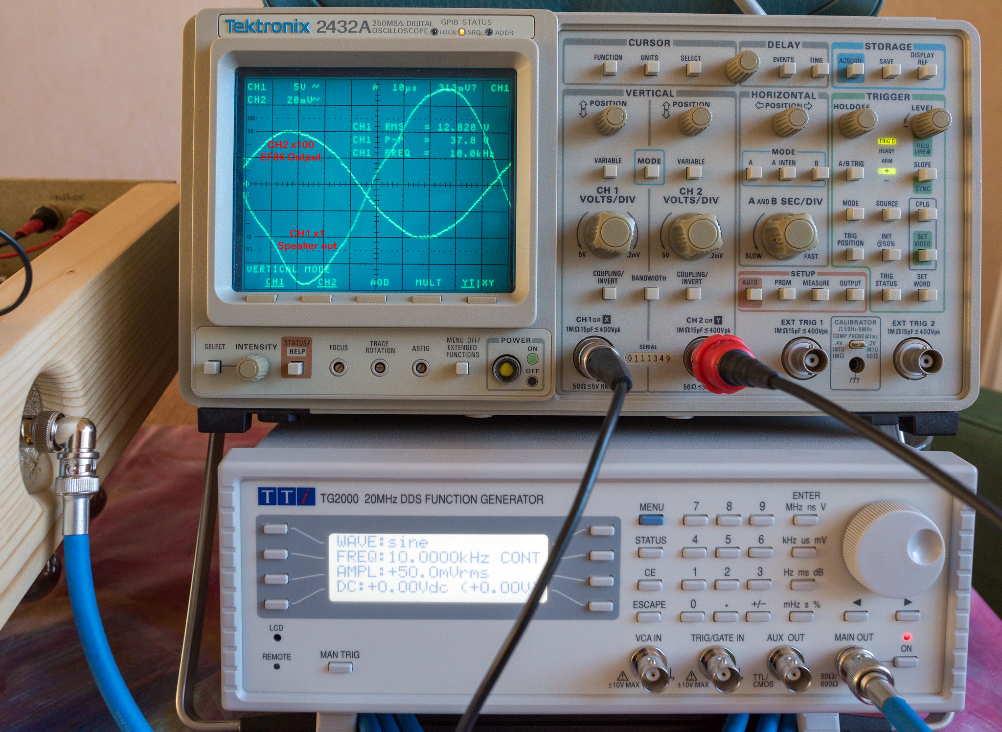
Here is a short video of it under a music test run with speaker attached. (not hifi sound here as the D810 mic isn't great)

I actually left it run for nearly 6 hours as it sounded great. Not a hint of red plating (anode hot spots) this time, all looks healthy in the glow department.
50152158083_c697b749b1_k.jpg

50152157783_0df5554180_k.jpg


In principal, I'm now left with the challenging part of closing the feedback loop and keeping things stable. No mean feat.
 
Back
Top Bottom