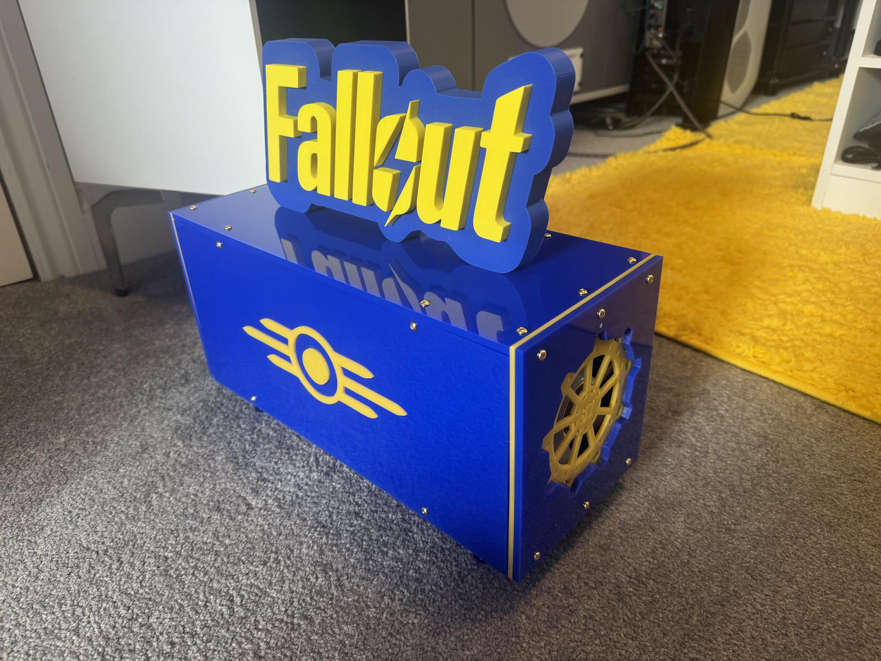
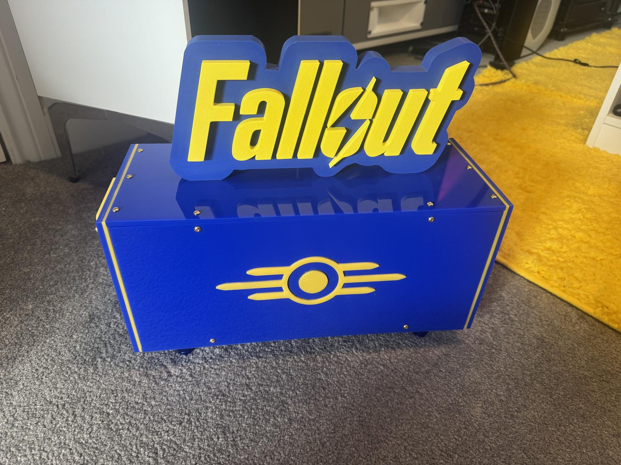
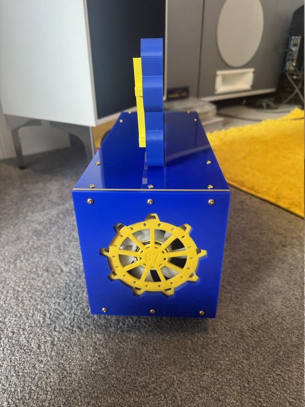
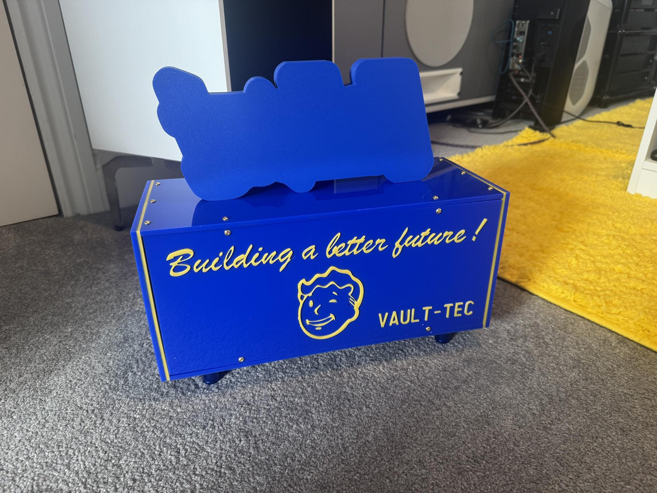
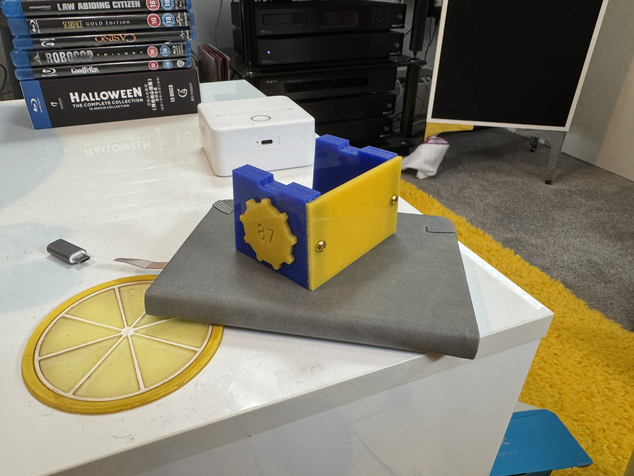
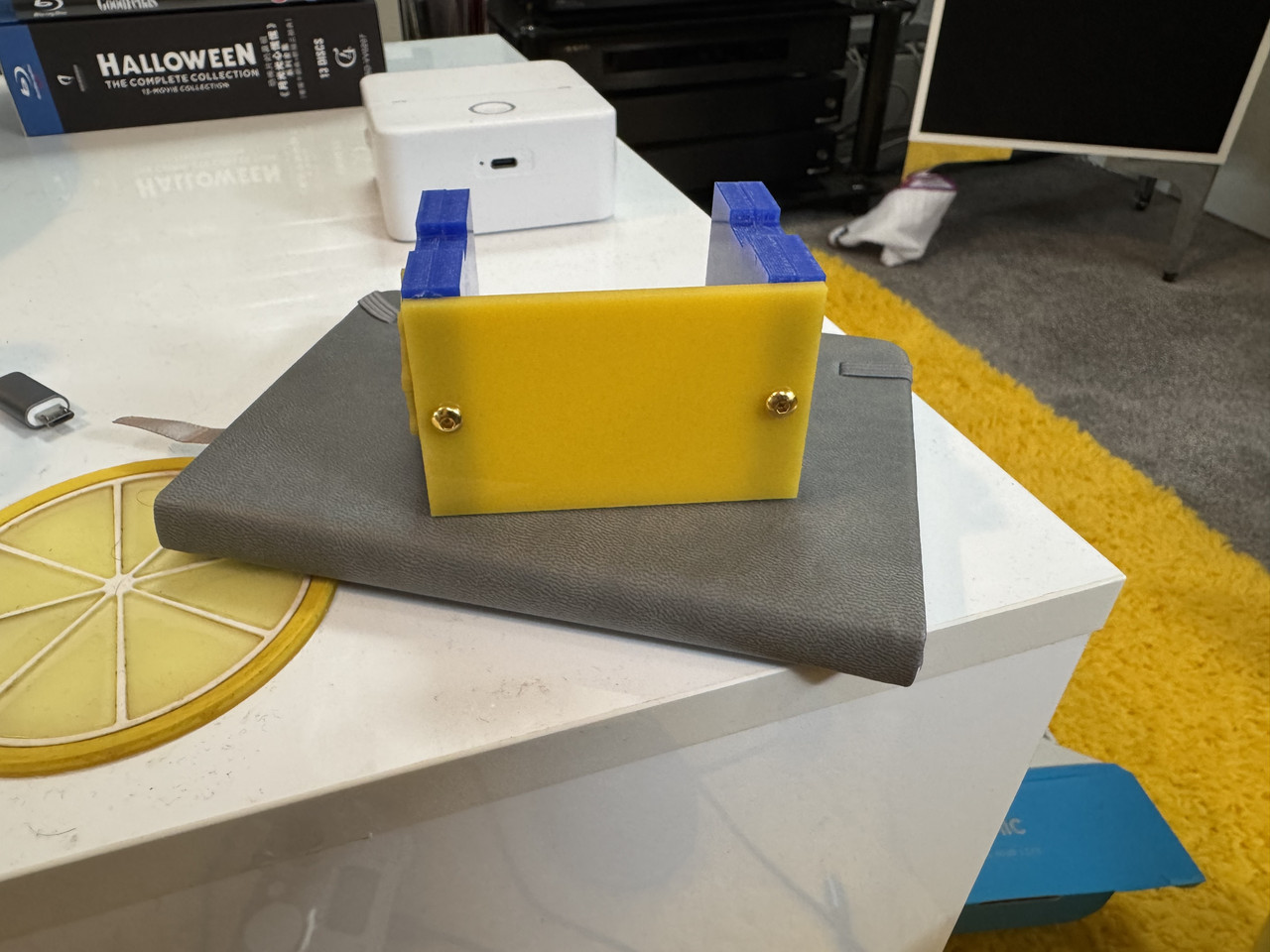
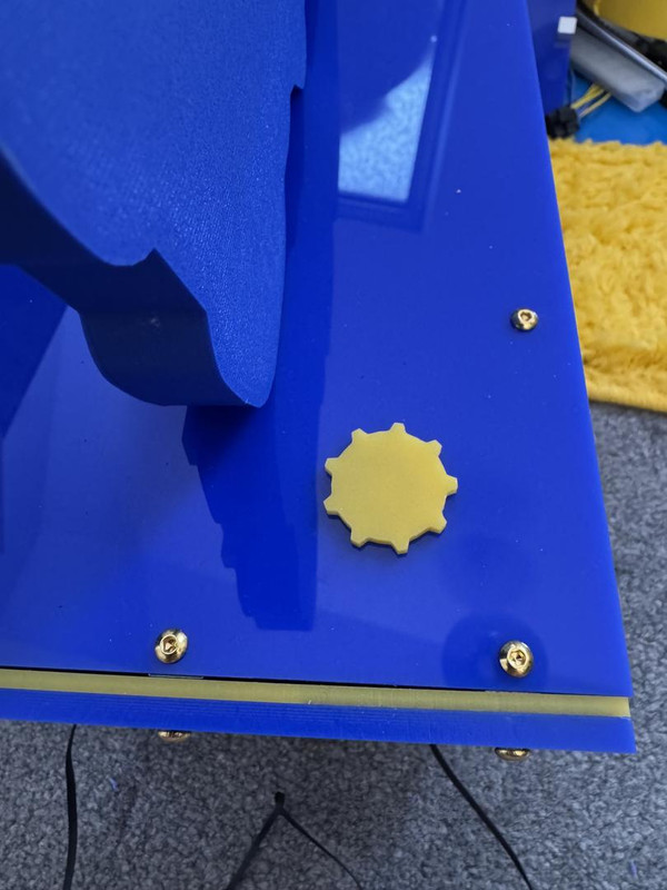
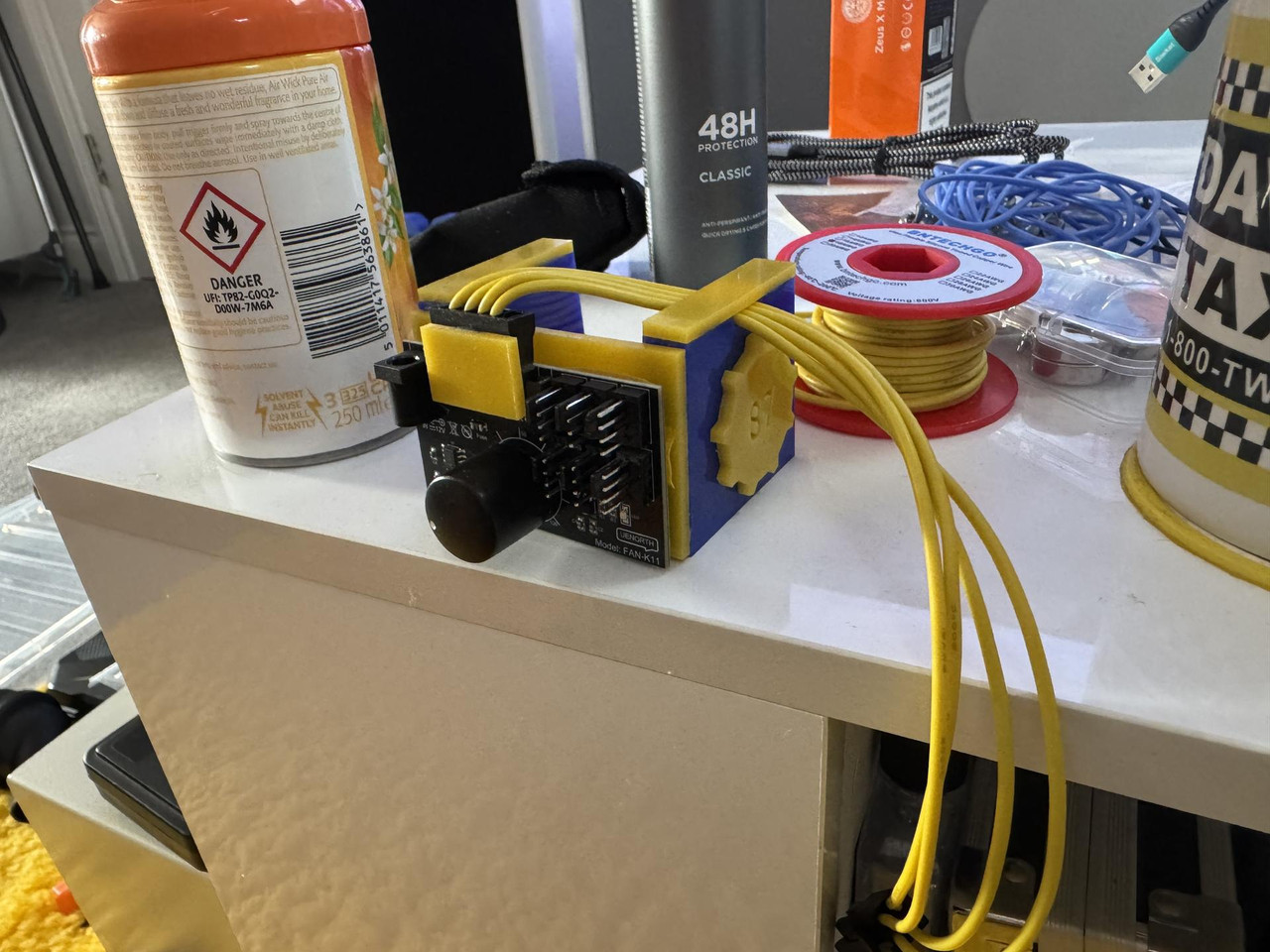
OK so a couple of days back I finished machining the spacers. This is a 1cm2 yellow 3mm piece and a 1mm2 5mm blue piece.
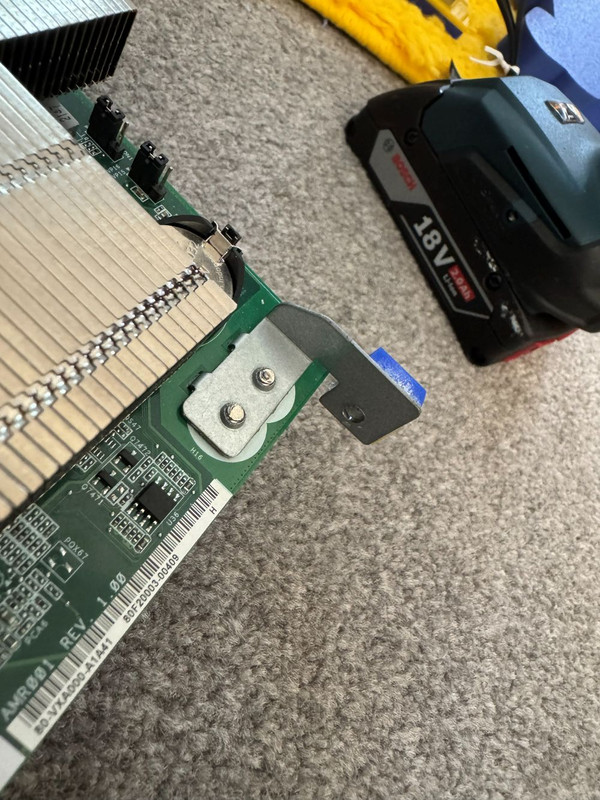
It's kinda messy as I needed to sand it all to make it stick together and theres some glue run out too. None of this matters obs as you will never see it.
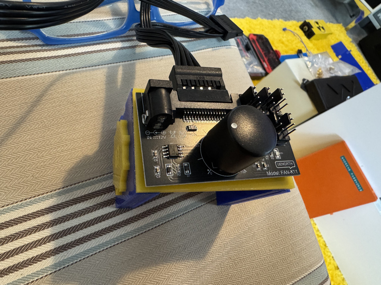
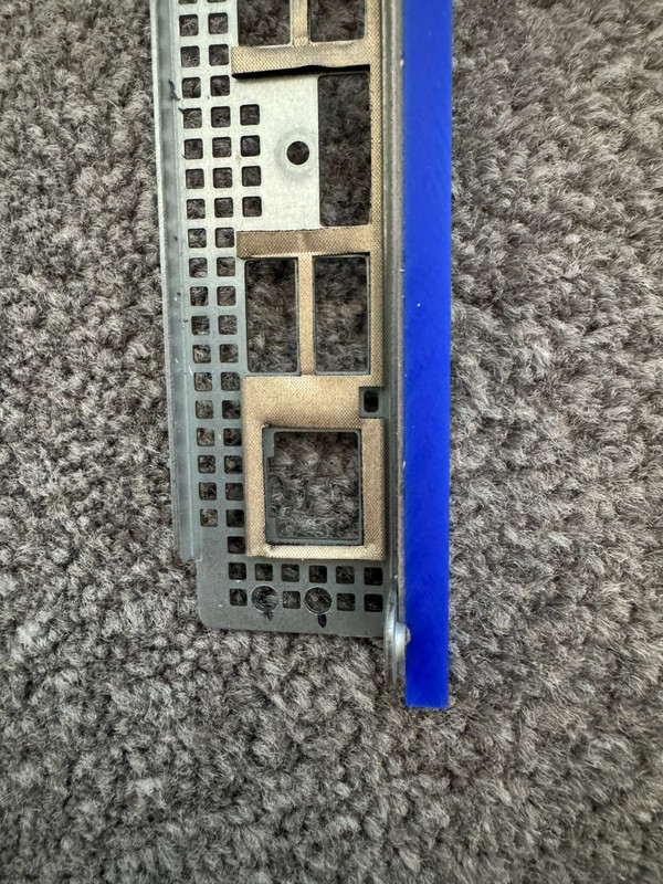
OK so with that mounting point sorted I moved onto the next one. This one was more difficult as I had not pre planned it. See, when you get to this bit you need to sort it as you go. It was the same with the other BC250 I did, and it all falls into place. So, the next idea was to basically use the IO as a hard mount. I drilled two of the small square holes out to 3mm....
And then.
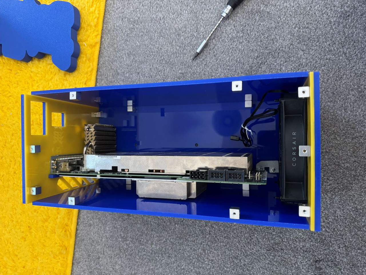
So how does it look? try this.
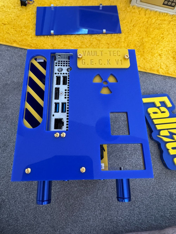
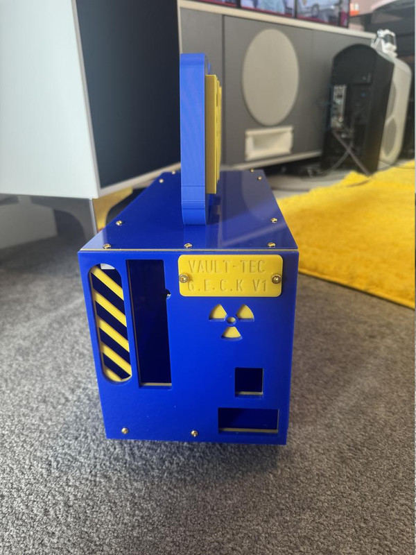
If you cast your mind back a lot of posts I mentioned having to shift it all 5mm. If you look at the IO you can see I glued on a piece of cut 5mm acrylic to fill this gap. I also mentioned I had to file out the back of the case so I could access both the power and reset switches on the IO. So, above is all of that completed.
My next worry if you will recall, and lots of worry was the heatsink I attached to the back with thermal epoxy. IE this tish ain't comin' off. This was why I had to move everything 5mm to gain the space to fit the right side panel. So, how are we looking?
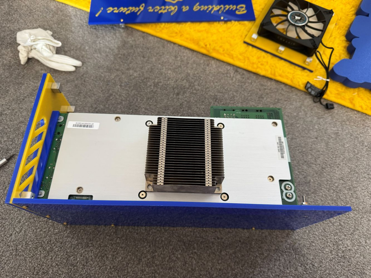
Kinda good but the proof is in the pudding. Does the side fit in there leaving room for it?
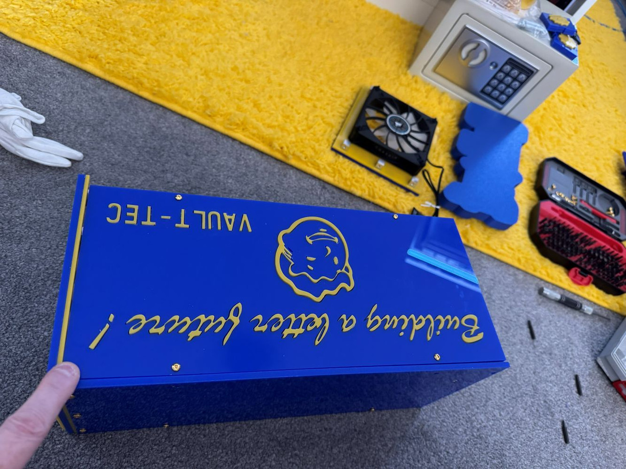
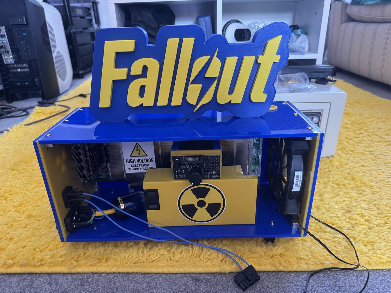
So here it is, mounted strongly and where it all should be.
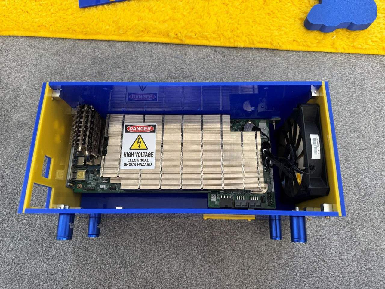
One of the other worries was how to plug in the power for the board. Did our hatch idea work? and more importantly is it in the right place? Thankfully that is a resounding yes.
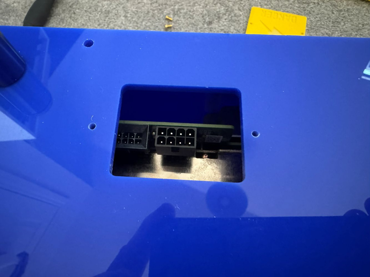
Phew. I won't lie, putting a quite expensive piece of acrylic back on the machine when you thought you were done is quite scary. It was also critical I did not mess up, as I blew my spare piece pretty much on day one when the software spazzed and made my vault door all peed.
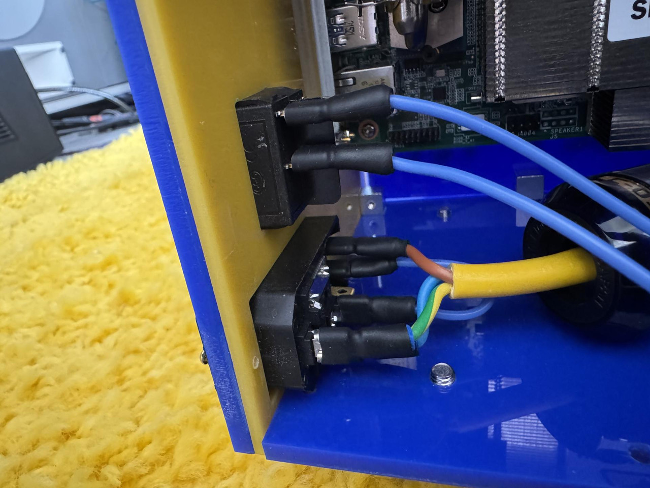
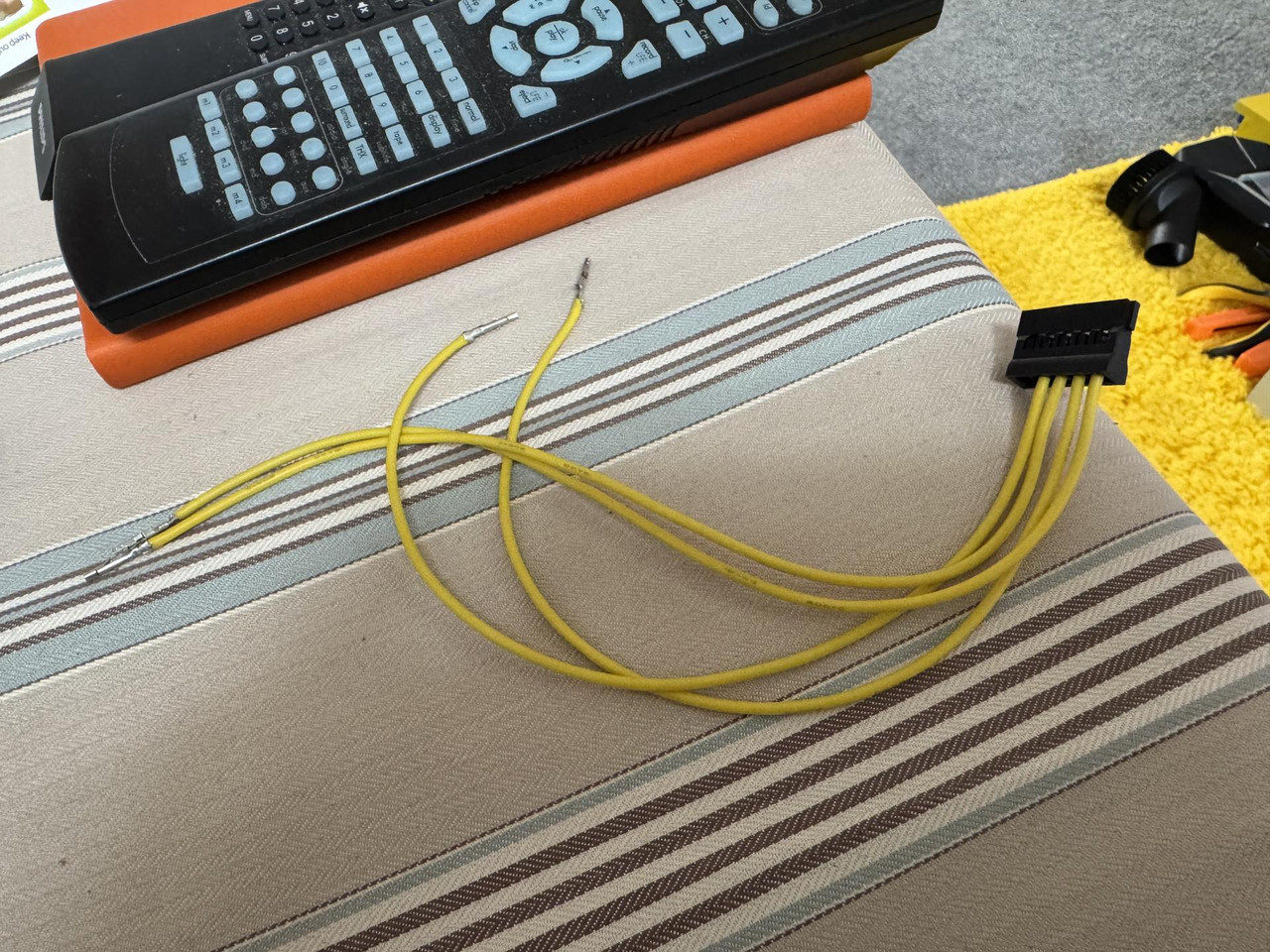
Right, so I knew now it was time to start thinking about wiring. And again, this was frightening. See, I chose an IEC socket for the back with a switch on. So it is not just as simple as plugging in the three wires and it works. No, this requires a jumper wire that I had to figure out then (last November) and the wires don't go where you would expect them to, as there is no pin for the live because it goes via the switch. And what would you know? I had 100% clean forgotten how it worked. Feg.
I decided in the end to connect up said switch, jumper and power leads as best as I could remember. Then, before even plugging the live hot end into the PSU and potentially blowing it and anything connected to it to pieces with a shorted 240v I decided to buzz each pin to make sure none of the wires were shorted. At least then I knew nothing expensive would explode, and hey either power would go through or not, but nothing would short and blow up !
And so, after doing everything I could to prevent disaster...... I held my breath, let out a slightly shaky fart, and.....
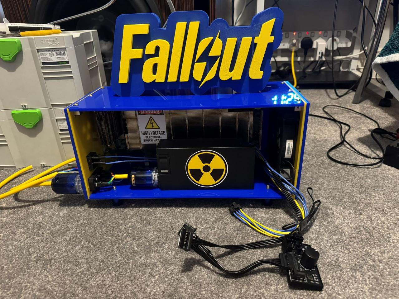
IT'S ALIVE !!
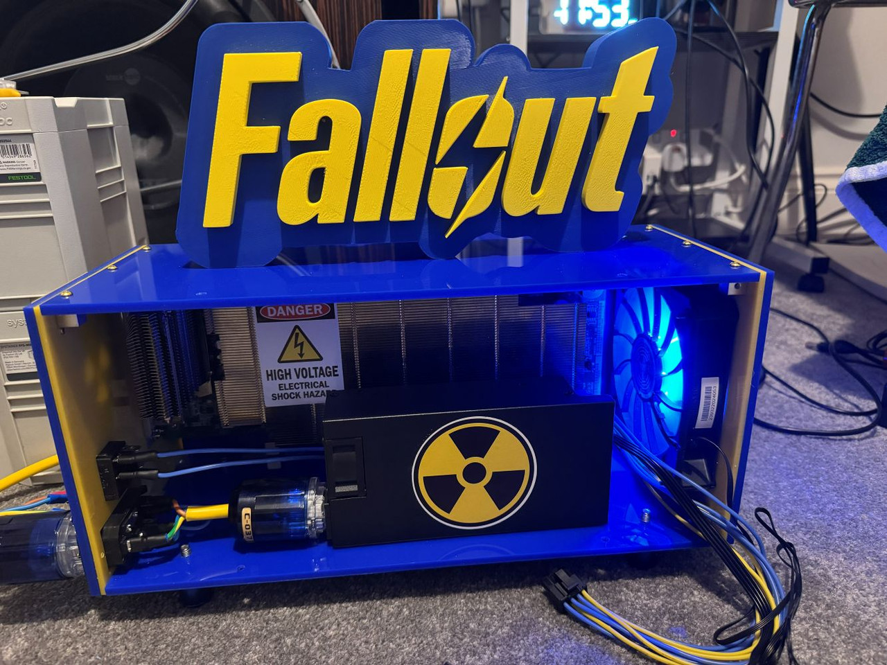
Corrr !
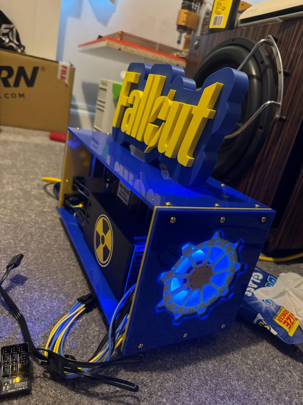
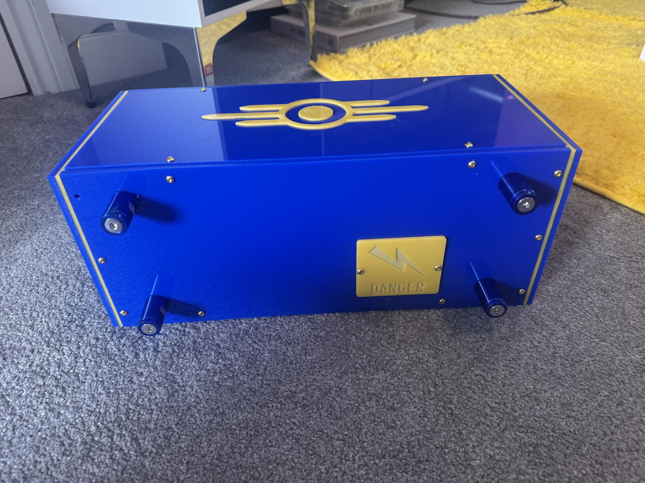
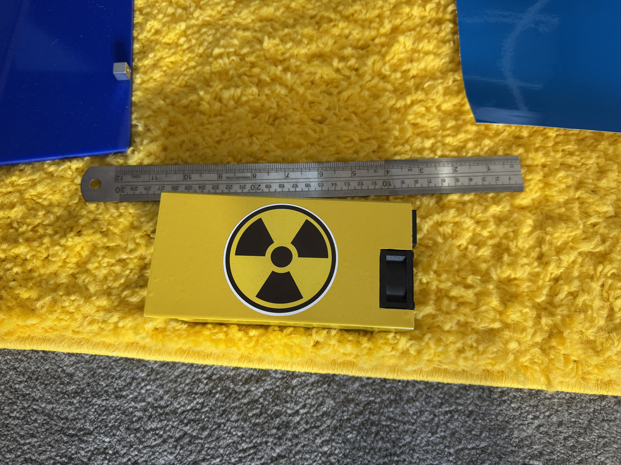
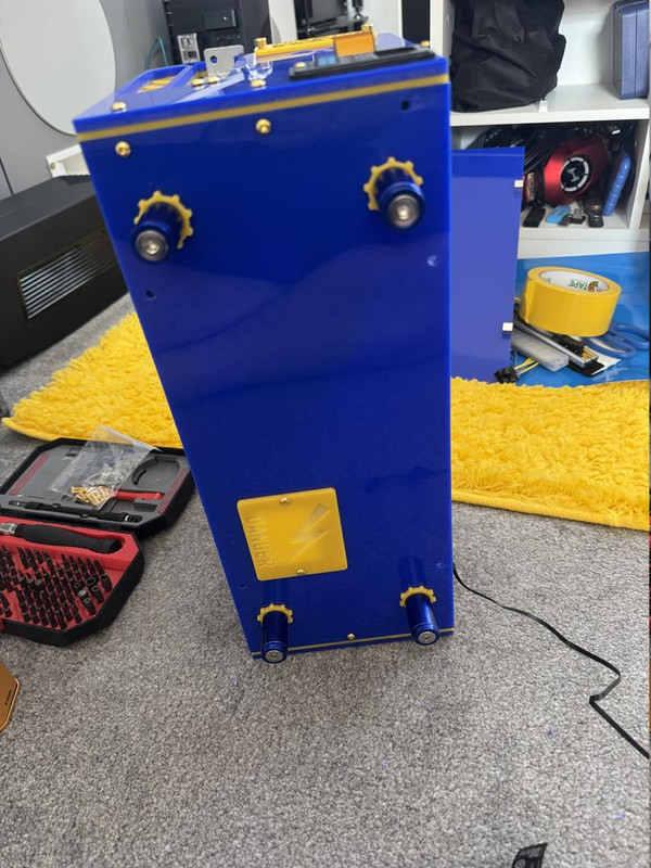
Now I still have work to do. Firstly there is now a 3mm countersunk bolt running in through a hole in the top panel. This will be captive too like the fan bolts, so I need to make a cover. It is what bolts into the tang end of the board. I also want to machine some vault door shaped feet "washers" to add some panache and a couple more pieces. Once that is done I am going to wrap the parts of the PSU you see with gloss yellow vinyl (ordered) and put another radiation sticker on (I have a sheet I bought for a bike years ago).
Once I am at that point I shall make the duct, and then be happy to send power into the BC250.