This may cause some heated discussion on some forums - the topic of rear axle and suspension.
Some will argue that the standard rear axle will be good enough for more power. My dad's experience says otherwise - in the early 70's he was breaking diffs with just a 1500GT engine and some aggressive starts - but those were the days when Anglias were easily found in scrap yards, and a diff could be broken on a Friday night, and a replacement sourced and fitted by lunchtime on Saturday.
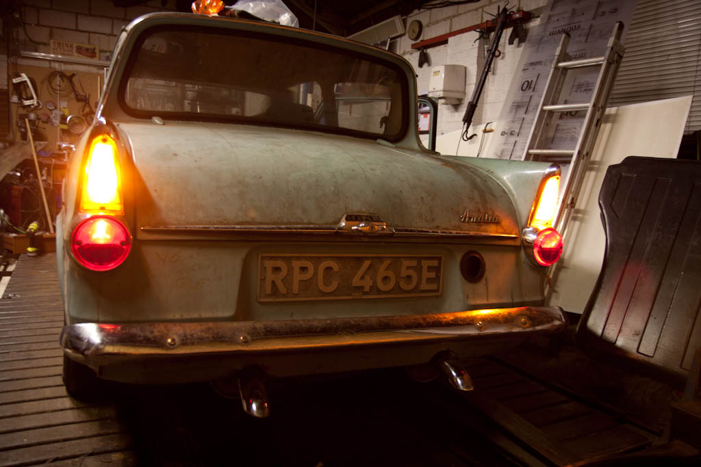
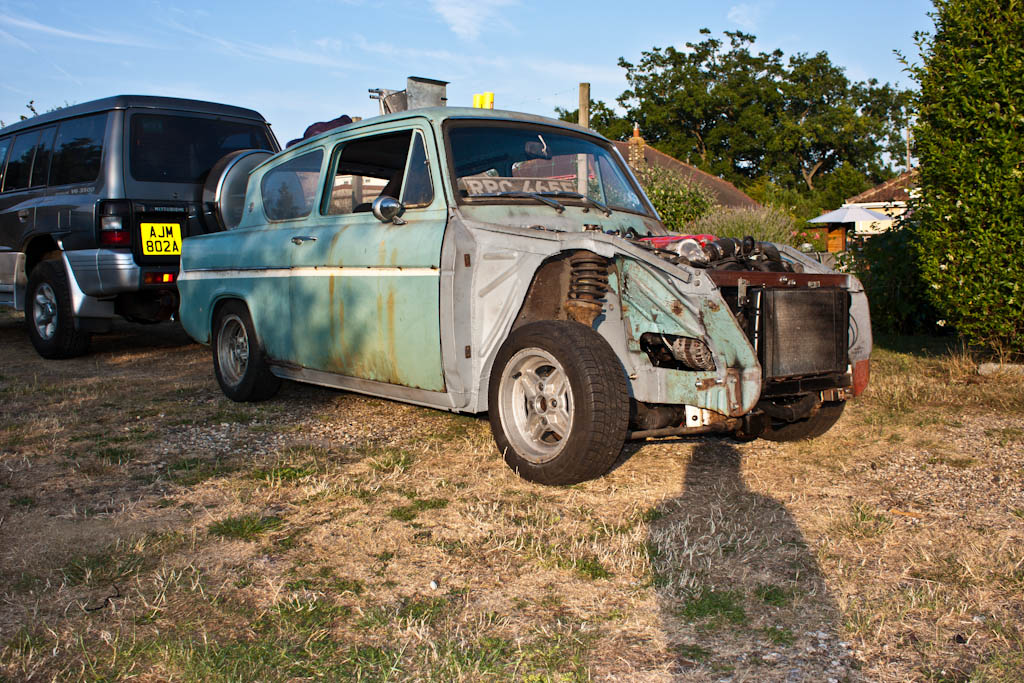
However, this is 2013, and parts for a Ford Anglia aren't as easy to come by now.
Therefore - I have decided that I do not want to use any parts of the original rear axle.
I am absolutely not putting wider arches on it, so a wider axle is also out of the question, which means something custom made.
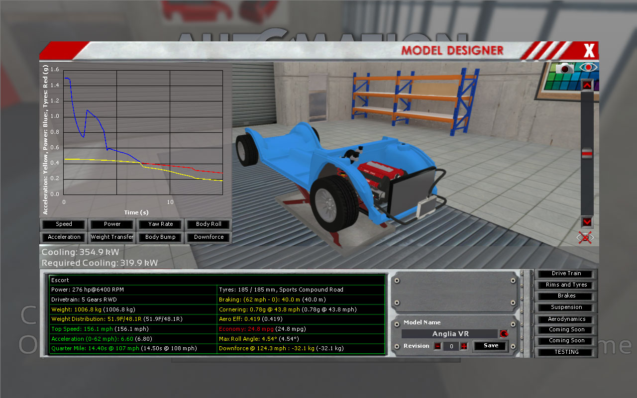
I have a perfectly good diff from the 200SX, which I know will take the ~300ft-lb of torque from the engine, as well as the rear hub units, so instead, I shall be making my own rear axle.
This will allow me to have it the exact width I need, using a diff that I know is good.
I had a long debate with my dad regarding what to do about rear suspension (since, in fact, when I purchased the 200SX), and we debated the original axle (not strong enough), and making either 1) a new live axle, 2) a de-dion tube or 3) fully independent
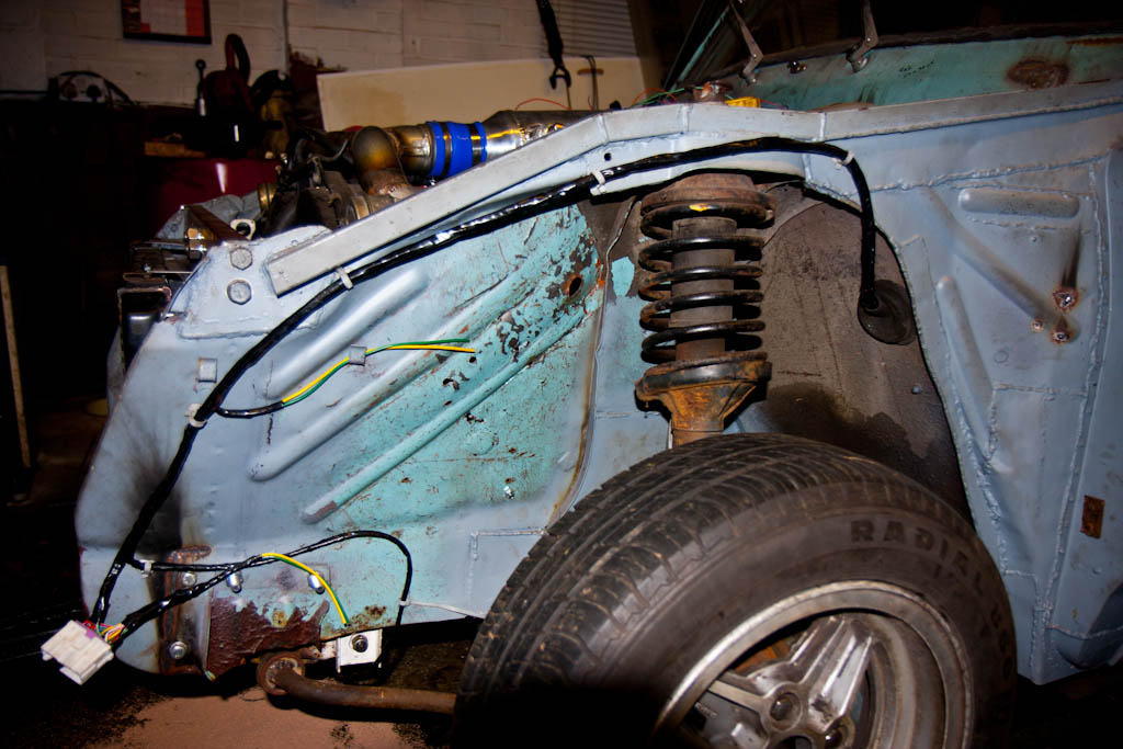
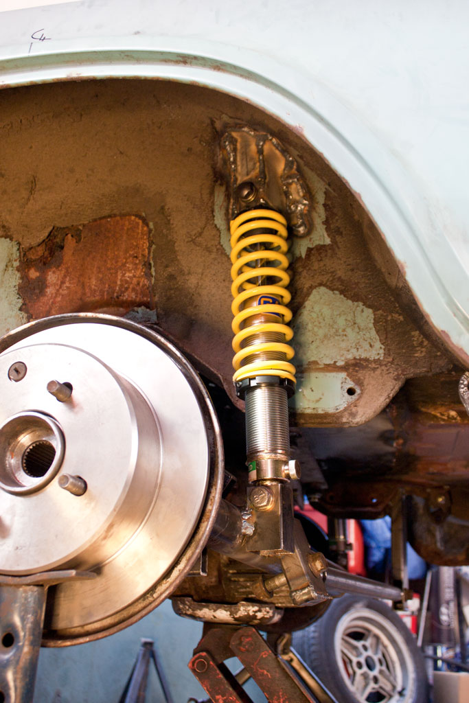
After discussion of the advantages and disadvantages of each, we decided on a de-dion tube setup. The wheels are linked together, much like a live axle, but instead of the diff being part of this, it is mounted to the floor, with a pair of driveshafts with CV joints to allow travel in the suspension. This will then have a 5-link setup to allow movement and location, with a pair of trailing arms on either side, and a panhard rod to prevent sideways travel of the axle.
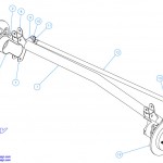
The above is a design by Rorty Designs, published a number of years back for the LocostBuilders site, based around Sierra parts to replace an Escort live axle on a Lotus-7 style kit car, and has been made by kit-car owners a number of times.
I will not be using Sierra bits (as I don't have any), so instead will be using this as a general idea of what to do based around the 200SX bits that I do have.
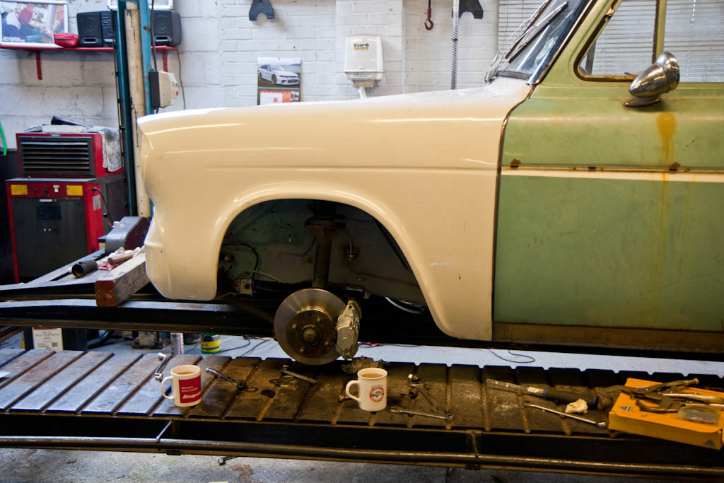
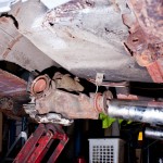
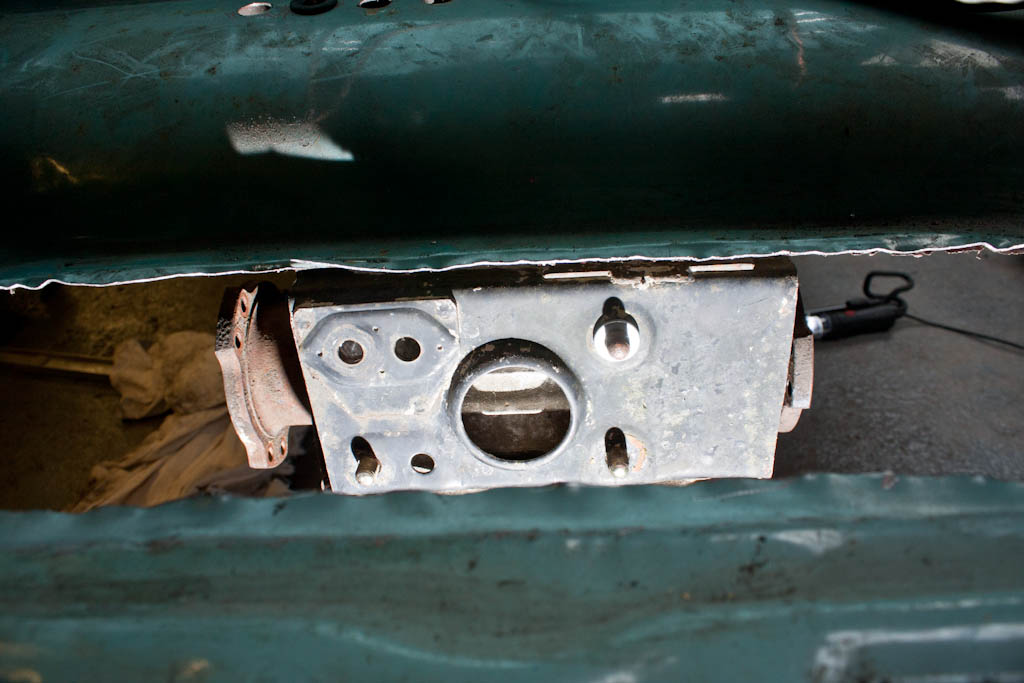
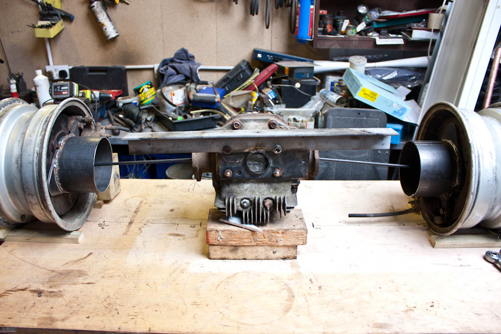
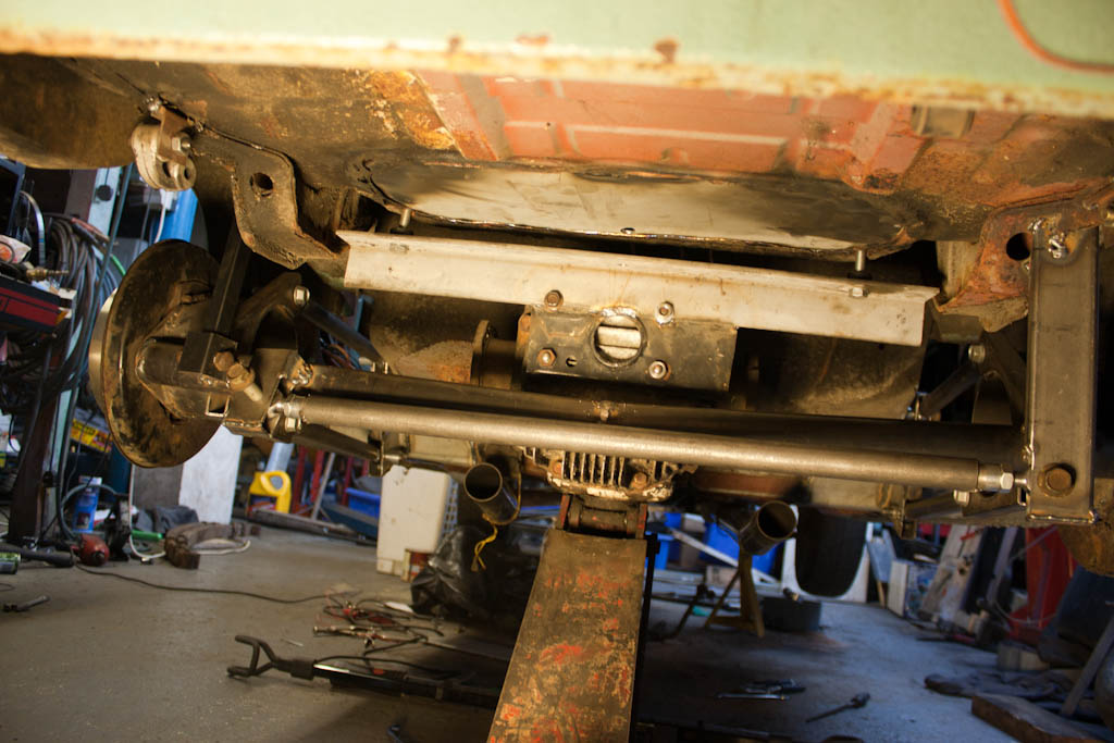
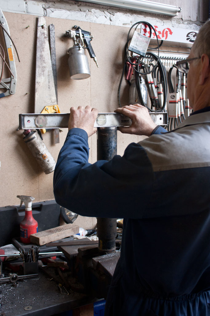
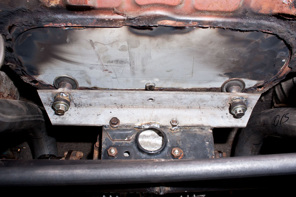
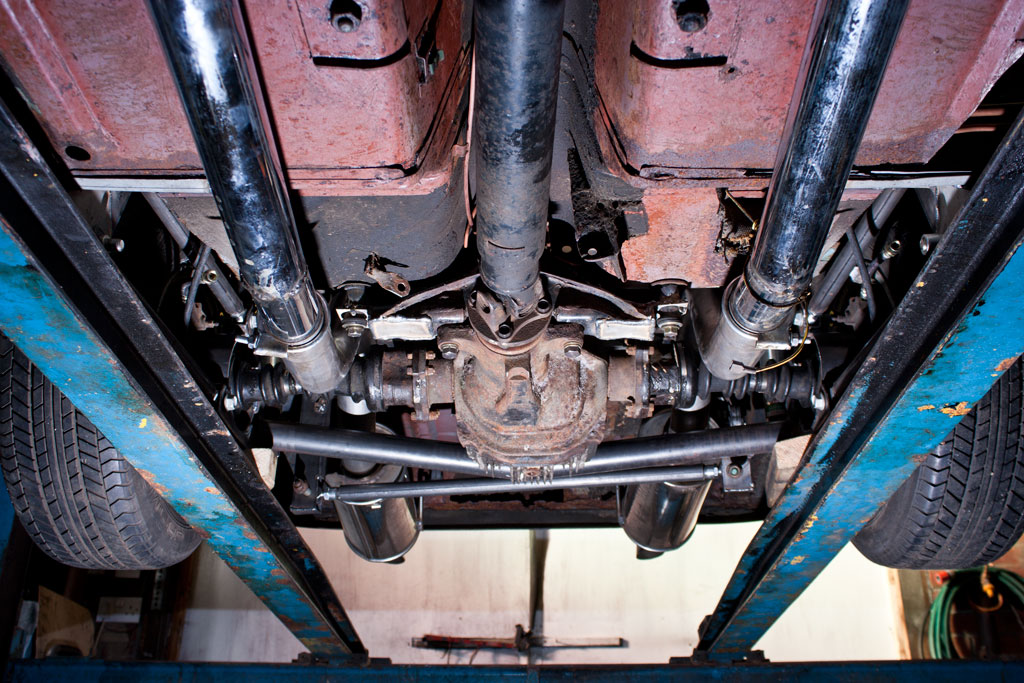
To begin, we set up a board with the wheels and diff, setting the wheels parallel and at the desired width to allow the wheels & tyres to sit within the confines of the standard wheelarches.
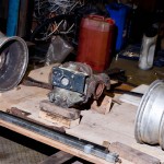
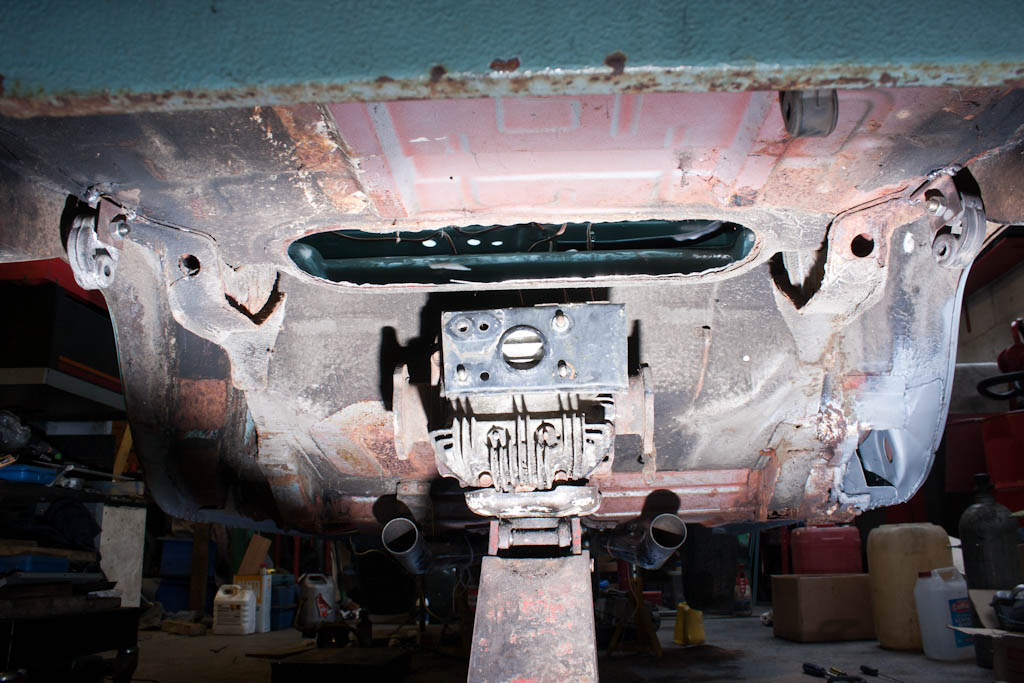
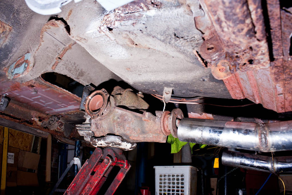
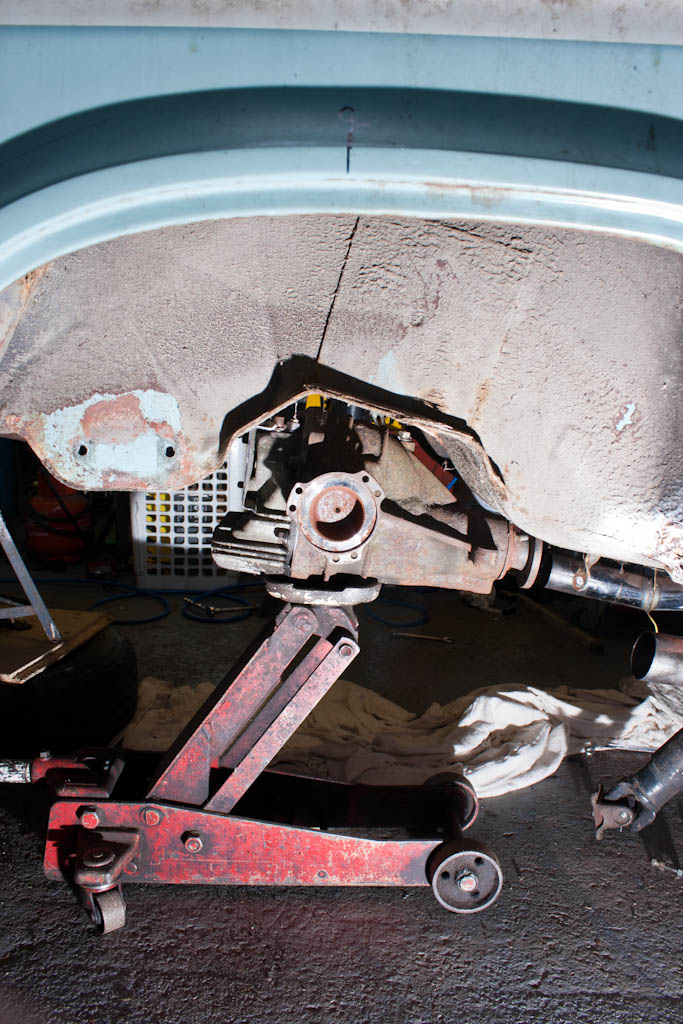
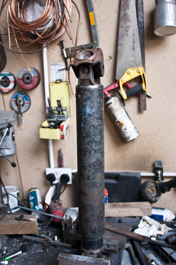
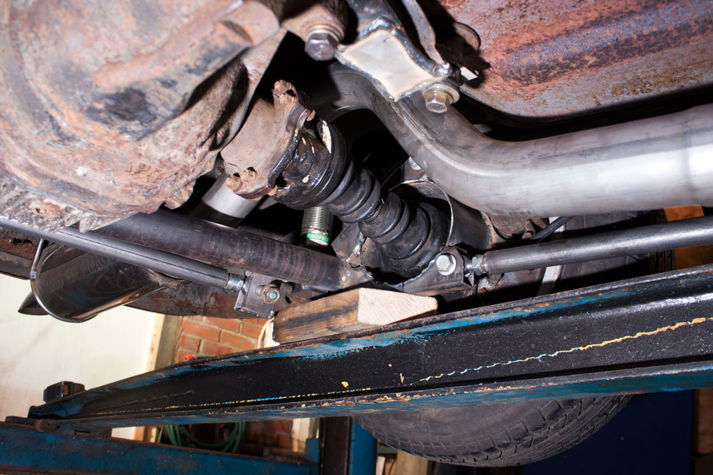
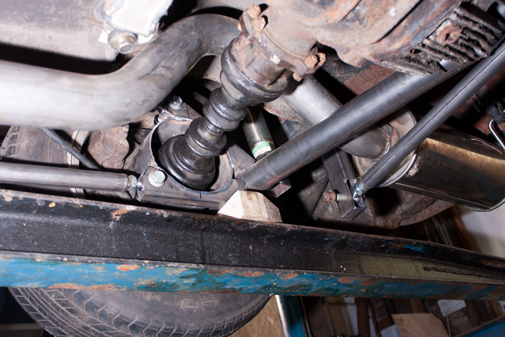
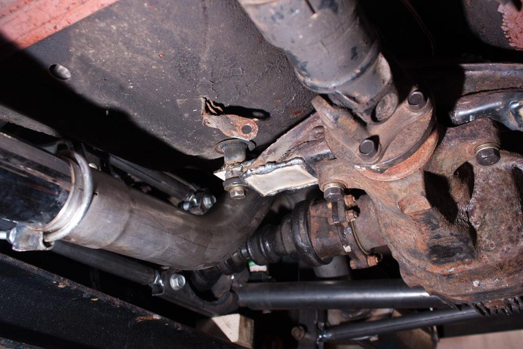
We then began to align the differential to the car, aligning it centrally (to give us equal length driveshafts) - which does mean that the nose will be slightly offset, but the propshaft has enough movement to allow this slight offset.
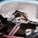
With the diff alignment mostly sorted, it was then time to look at the de-dion part of the suspension.
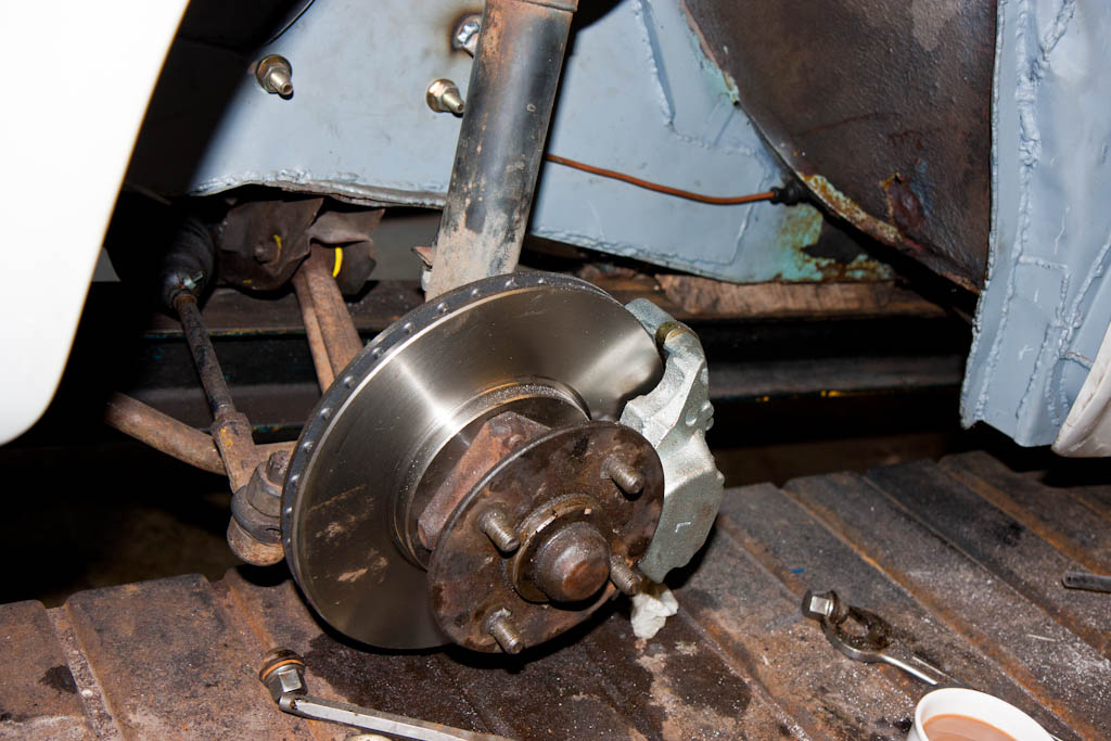
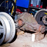
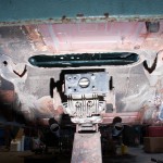
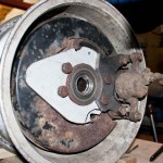
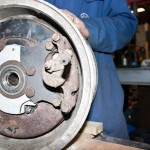
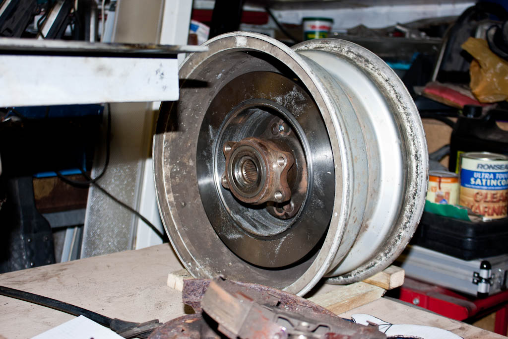
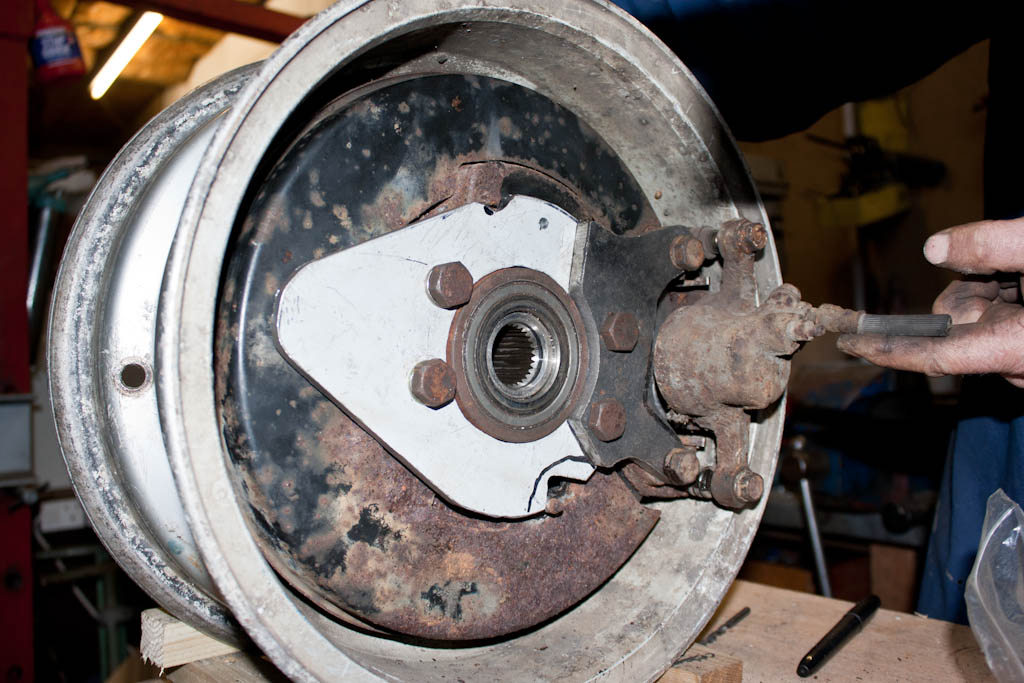
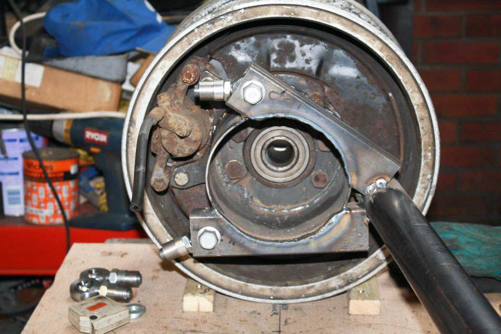
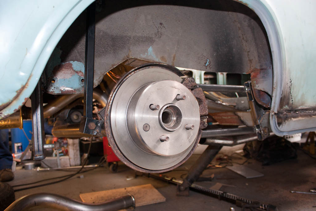
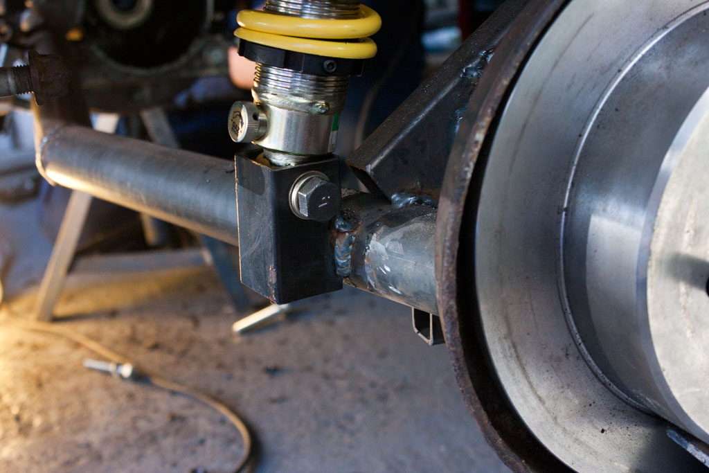
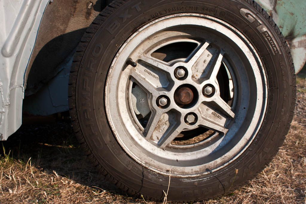
In order to attach the hubs, we need to make up some plates to affix this tube to the bearings. Firstly, was to strip down the 200SX rear hubs, and leave ourselves with the wheel bearing and brake disc assembly. The 265mm discs fit nicely under the 13" Ford wheels.
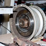
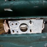
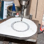
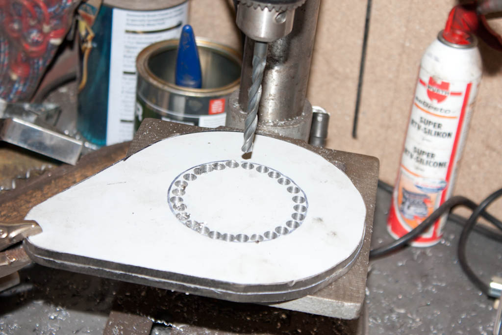
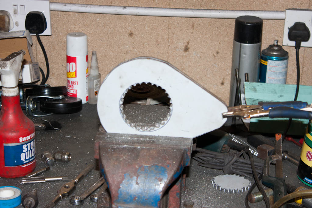
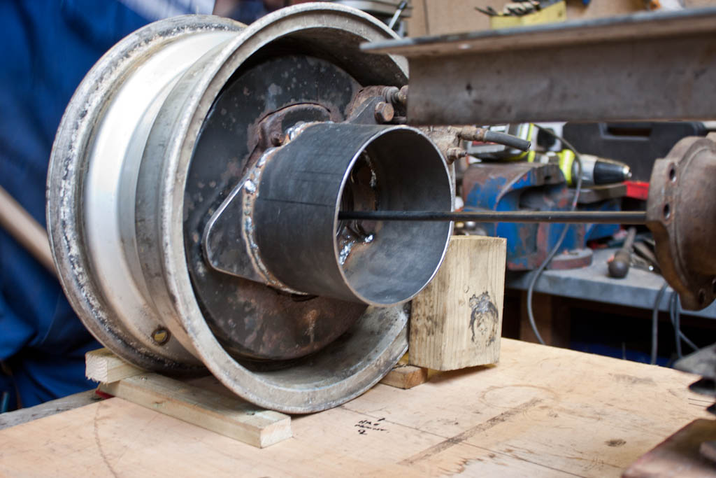
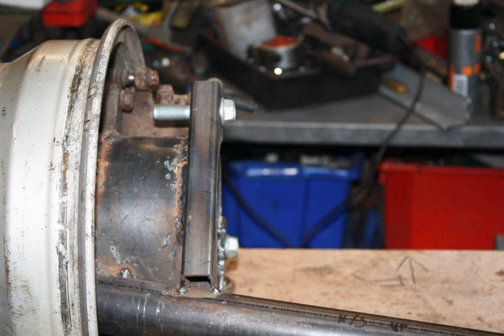
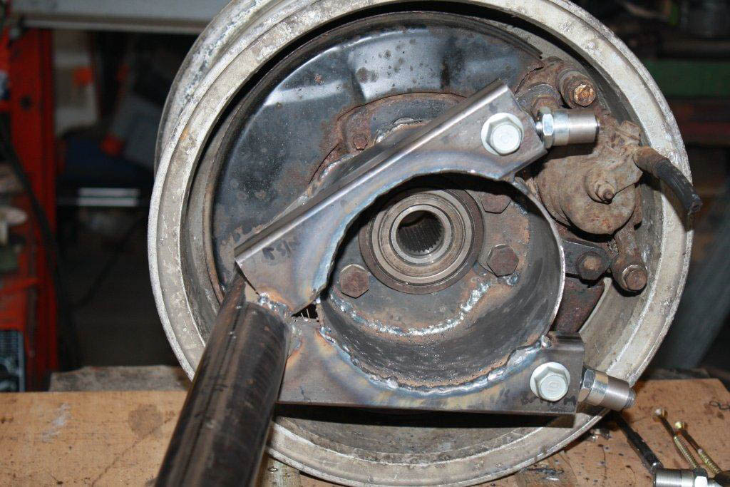
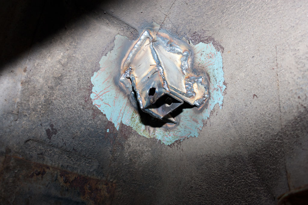
We then start with a template, which will be the first piece of the puzzle. This will bolt to the wheel bearing, and will have the de-dion tube attached to (#2 in the above plans).
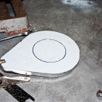
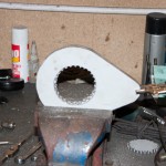
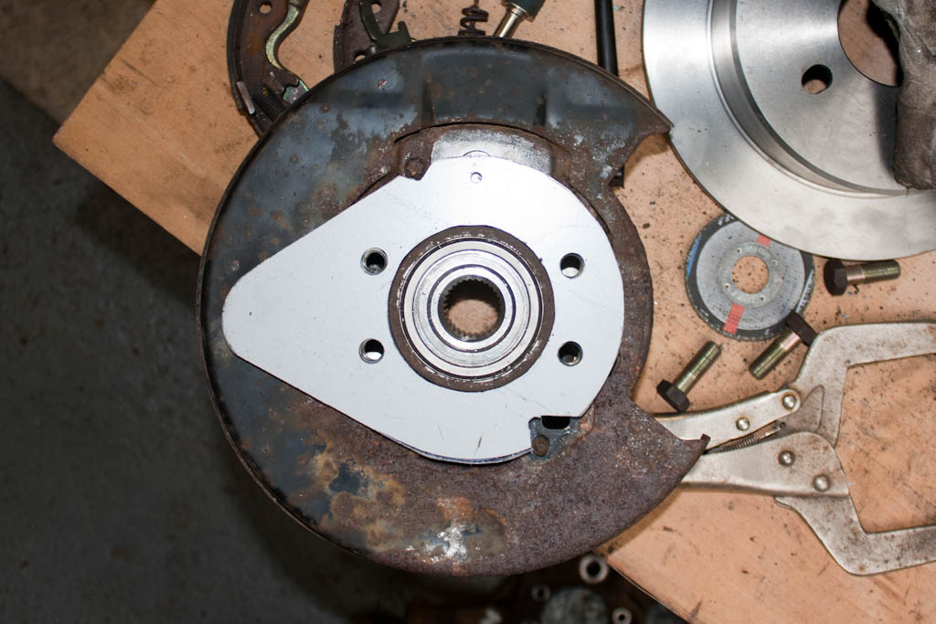
When this was cleaned up, it was attached to the bearing unit.
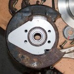
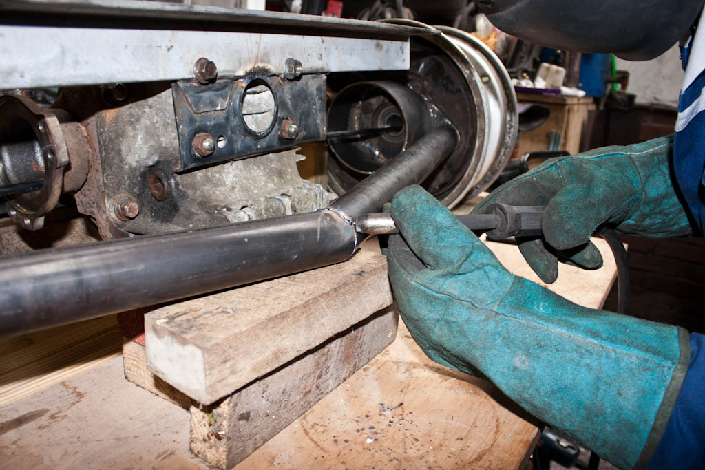
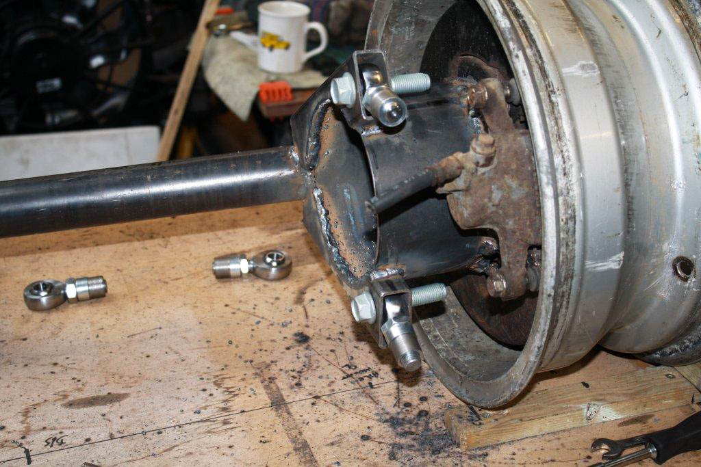
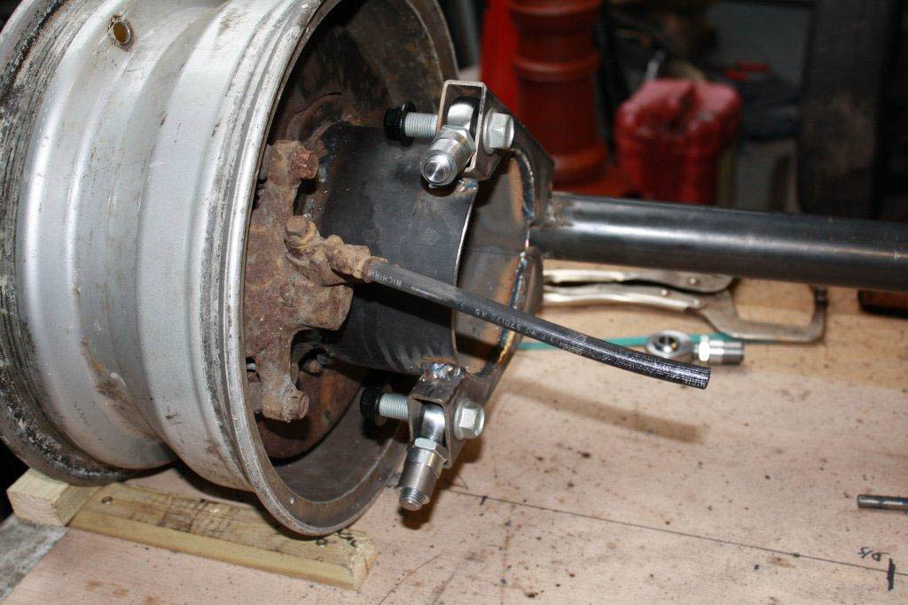
Caliper mounts (#3 in the above plans) were then made to take the 200SX brakes, putting them in the correct position, giving plenty of clearance within the wheels.
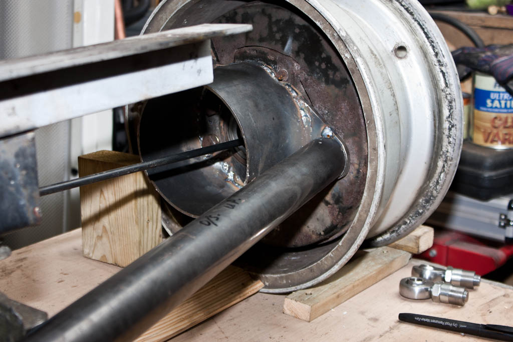
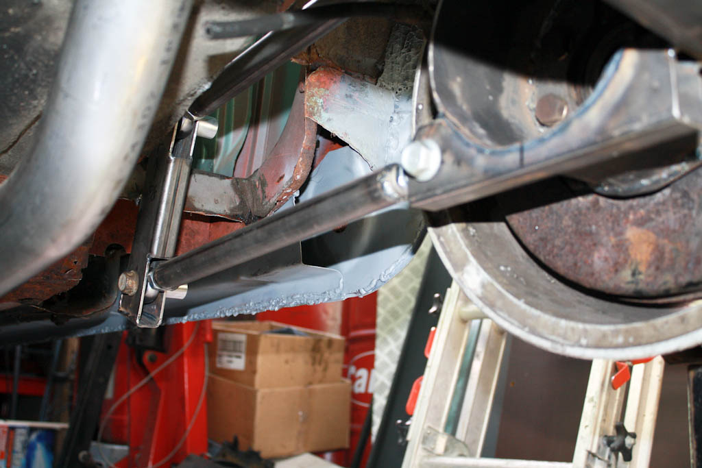
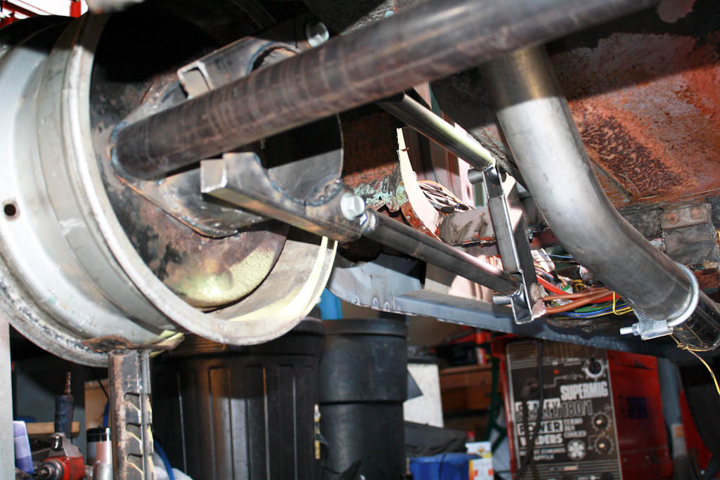
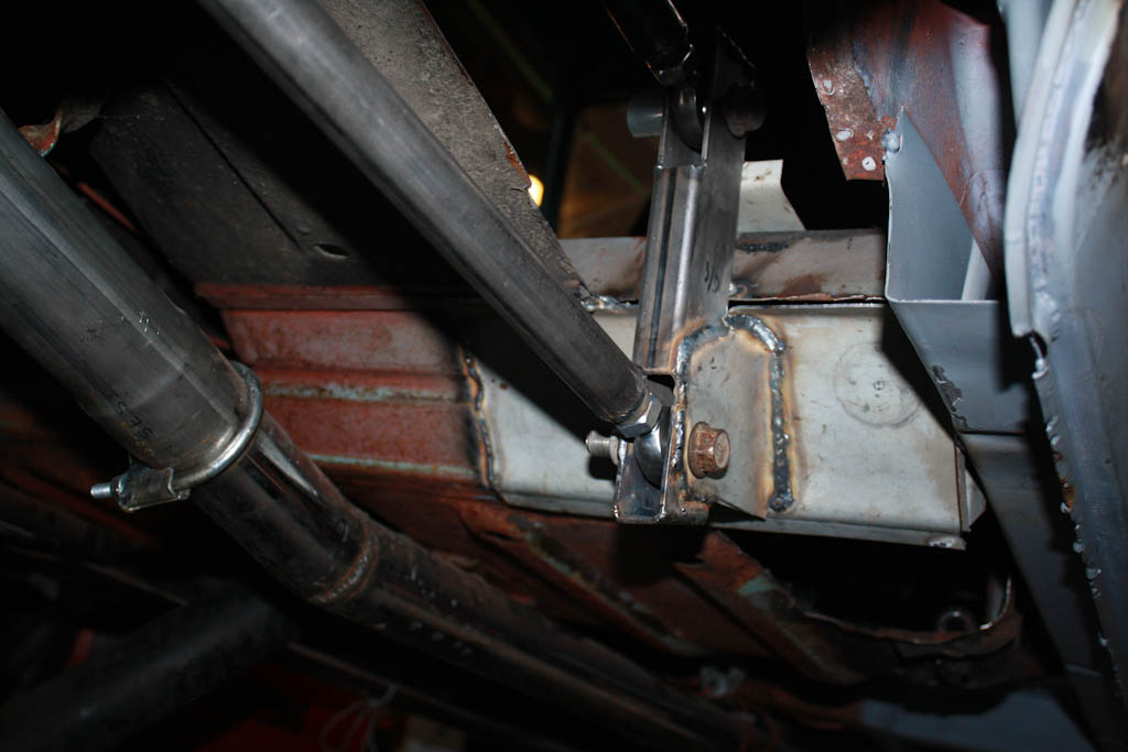
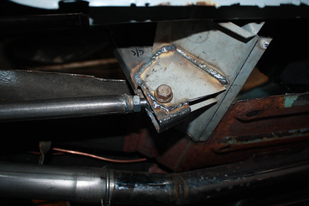
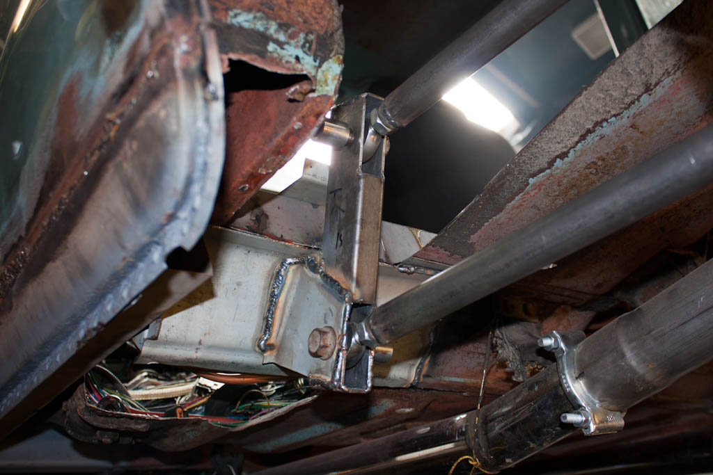
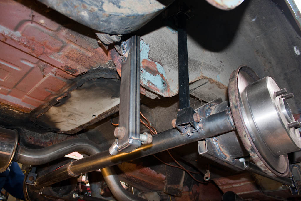
Next is to make the hub bucket (#6 in the above plans), attach the main de-dion tube (#1), and make up the trailing arm brackets (#7), trailing arms, panhard rod (#12) and the other little brackets to affix.
Some will argue that the standard rear axle will be good enough for more power. My dad's experience says otherwise - in the early 70's he was breaking diffs with just a 1500GT engine and some aggressive starts - but those were the days when Anglias were easily found in scrap yards, and a diff could be broken on a Friday night, and a replacement sourced and fitted by lunchtime on Saturday.
However, this is 2013, and parts for a Ford Anglia aren't as easy to come by now.
Therefore - I have decided that I do not want to use any parts of the original rear axle.
I am absolutely not putting wider arches on it, so a wider axle is also out of the question, which means something custom made.
I have a perfectly good diff from the 200SX, which I know will take the ~300ft-lb of torque from the engine, as well as the rear hub units, so instead, I shall be making my own rear axle.
This will allow me to have it the exact width I need, using a diff that I know is good.
I had a long debate with my dad regarding what to do about rear suspension (since, in fact, when I purchased the 200SX), and we debated the original axle (not strong enough), and making either 1) a new live axle, 2) a de-dion tube or 3) fully independent
After discussion of the advantages and disadvantages of each, we decided on a de-dion tube setup. The wheels are linked together, much like a live axle, but instead of the diff being part of this, it is mounted to the floor, with a pair of driveshafts with CV joints to allow travel in the suspension. This will then have a 5-link setup to allow movement and location, with a pair of trailing arms on either side, and a panhard rod to prevent sideways travel of the axle.
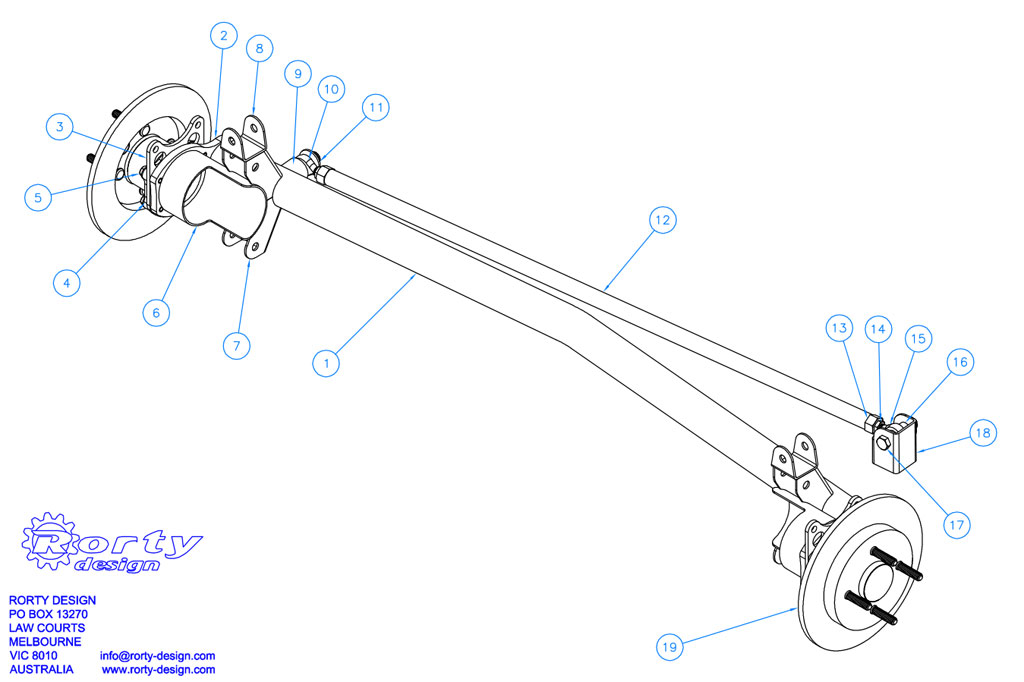
The above is a design by Rorty Designs, published a number of years back for the LocostBuilders site, based around Sierra parts to replace an Escort live axle on a Lotus-7 style kit car, and has been made by kit-car owners a number of times.
I will not be using Sierra bits (as I don't have any), so instead will be using this as a general idea of what to do based around the 200SX bits that I do have.
To begin, we set up a board with the wheels and diff, setting the wheels parallel and at the desired width to allow the wheels & tyres to sit within the confines of the standard wheelarches.
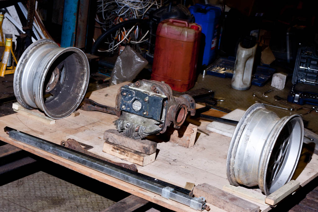
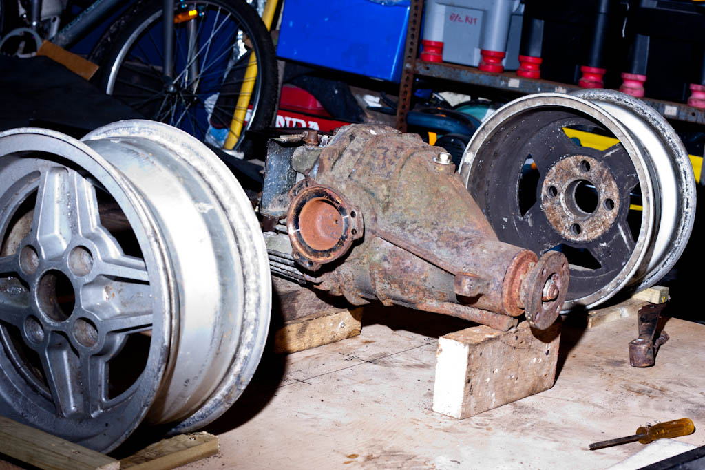
We then began to align the differential to the car, aligning it centrally (to give us equal length driveshafts) - which does mean that the nose will be slightly offset, but the propshaft has enough movement to allow this slight offset.
With the diff alignment mostly sorted, it was then time to look at the de-dion part of the suspension.
In order to attach the hubs, we need to make up some plates to affix this tube to the bearings. Firstly, was to strip down the 200SX rear hubs, and leave ourselves with the wheel bearing and brake disc assembly. The 265mm discs fit nicely under the 13" Ford wheels.
We then start with a template, which will be the first piece of the puzzle. This will bolt to the wheel bearing, and will have the de-dion tube attached to (#2 in the above plans).

When this was cleaned up, it was attached to the bearing unit.
Caliper mounts (#3 in the above plans) were then made to take the 200SX brakes, putting them in the correct position, giving plenty of clearance within the wheels.

Next is to make the hub bucket (#6 in the above plans), attach the main de-dion tube (#1), and make up the trailing arm brackets (#7), trailing arms, panhard rod (#12) and the other little brackets to affix.
Last edited:


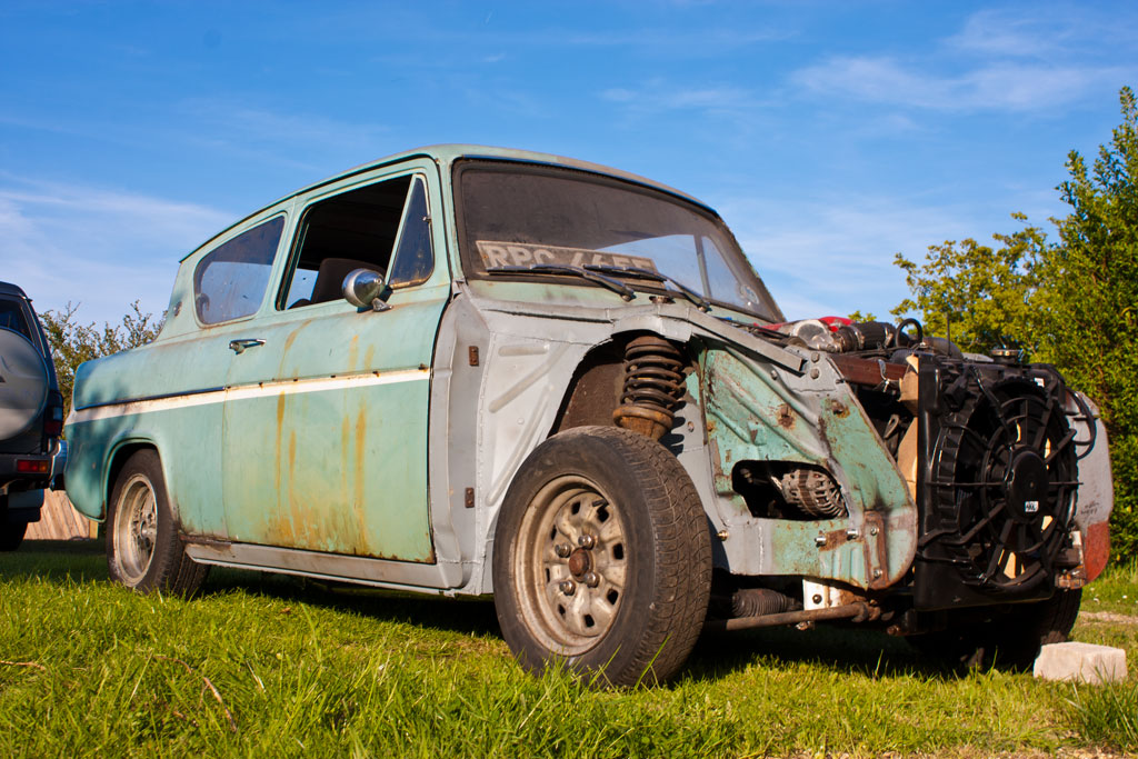


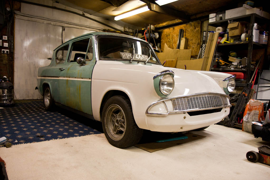
 you should keep the paint as is with a nice clear coat on it .
")
")