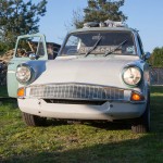
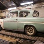
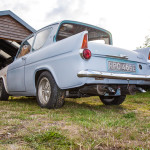
Anglia Project

Following on from last time, I have now completed the wiring to the front end, with indicators, side repeaters and headlights now all wired up and working.


When browsing forums, I found someone who was selling a MAP-ECU 2 - the next version of the MAP-ECU which I already have installed (the little box of tricks that allows removal of the MAF sensor) - the newer model adds a few new features - ignition timing control, two switchable maps, electronic boost control, air/fuel ratio adjustment, fuel cut removal, speed cut removal, and launch control.

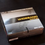
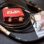
I paired this with a wideband O2 sensor/controller, which provides a very accurate air/fuel ratio to the MAP-ECU2, as well as a simulated narrowband output to the stock ECU.

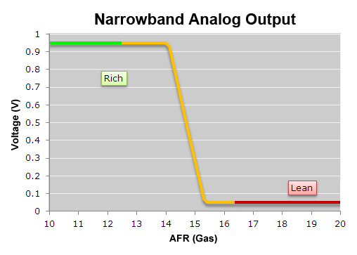
A standard narrowband O2 sensor as fitted to most vehicles operates by switching the output between 0v and 1v when the air/fuel ratio (AFR) goes either side of the stoichiometric point - the point at where all fuel is evenly burned with all of the available air - with petrol this is an AFR of 14.7, or lambda 1.00

The narrowband O2 sensor is used by the ECU to adjust the amount of fuel - an input value of 0v means "add more fuel" and an input value of 1v is "less fuel" - under normal use, the standard ECU will adjust the fuelling to ensure that the input voltage from the O2 sensor is rapidly fluctuating between 0v and 1v - this keeps the engine around lambda 1.00

This is shown by the following graph (graphs taken from the PLX website)
AFRNBGas_Analog.png


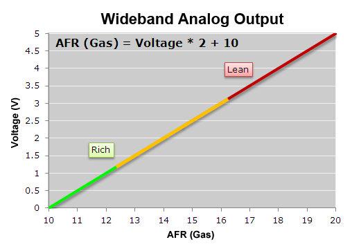
The wideband O2 sensor gives a voltage output which is directly related to the AFR, typically from 0v to 5v. The PLX SM-AFR I have provides a linear output and can show the AFR from 10:1 to 20:1 (lambda 0.68 to 1.36), as demonstrated by the following graph (again, taken from the PLX website)
AFRWBGas_Analog.png


When running under load, you may not want an AFR of 14.7 - you may want to run richer (more fuel), say at an AFR of 12 - with a narrowband O2 sensor, you have no way of telling what your AFR is, only that it's "rich" or "lean". With the wideband, I can monitor this via the MAP-ECU2, and adjust the fuelling accordingly to reach that target.

The MAP-ECU2 came from another VR-4, and the configuration that's on it is much better than the one that came on the original MAP-ECU I had (which also came from a VR-4) - the new one idles even better, and the lag that I had when pressing the throttle has disappeared. Even just this change is worth the money spent on it, as it puts it a lot closer to what's needed, which will hopefully reduce the need for an immediate expensive tuning session!

In addition to this, I received a nice package from ETB Instruments consisting of a 52mm fuel gauge, a 52mm temperature gauge, an 80mm electronic programmable speedometer and an 80mm tachometer.

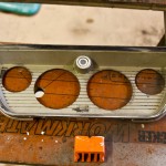
I am fitting these to a glove box lid, so I started by marking up and drilling out the necessary mounting holes:


It was then time to fit the dials, and wire them up to a connector plug to allow easy removal from the rest of the wiring loom.
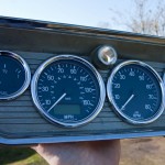
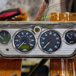

The new speedometer is programmable so it can be used with a wide variety of speed sensors and can be programmed to suit your wheel/tyres, diff and gearbox - and any changes to any of these the speedometer can be reprogrammed very easily - if I had a mechanical speedometer, I'd need to send it off for recalibration if I ever made any changes.

It also provides the following features:
2 trip counters
0-xxmph time (comes as default set as 0-60mph)
1/4 mile time
Max speed recall
In built indicator lamps

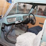
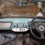
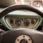
I also fitted a 3-spoke Momo steering wheel from an Evo 6, which is slightly smaller than the standard wheel from the VR-4, and placed the dials in place (but the glove box lid is not secured to the dash properly yet)


Whilst I was fiddling with wiring and electronics, my dad was concentrating on welding, and we now have the passenger side rear suspension mount and floor completed, as well as the exhausts now properly mounted on cotton reel mounts, rather than suspended from bits of electrical wire.
 
Nice job on the axle, but keep an eye on the welded join in the middle. This is under a lot of stress when cornering in one direction (with the axle in compression) and there were a few instances of these breaking on Locosts some years back. A bent tube would be a nicer design though not easy to DIY.

I presume there is going to be a diagonal brace added for the panhard rod chassis mounting?
 
Yes, an area to keep an eye on for definite - thanks for the heads up! I'm still thinking about going fully independent - a failure or weakening of that weld on the de-dion might be a good reason to revisit the rear suspension ;)

We have added an additional brace to the panhard chassis mounting in a bout of welding a while back - obviously forgot to photograph it!
 
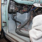
I didn't put up any photos of the front end last time out, and although the wiring was done, it wasn't tidy, so, spent some time tidying up the remainder of the wiring, both on the front end, and under the dash, taping up any loose bit of wire! Over all, I must have used well over a roll and a half of insulating tape!


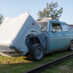
Also, the key locks to secure the flip front in place, and some lengths of chain were added to limit how much it opens - this gives good access across to the top of the engine, without putting the front too close to the floor. The wiring was secured by fibreglassing some cable ties onto the inside of the front, which create loops to put a further cable tie through - meaning if I need to remove the wiring loom (for example for painting), I can easily do so, and re-attach it again at a later date.


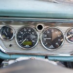
With the dash in finally (and the wiring loomed up, as mentioned earlier), I thought I'd take a photo of the gauges working - I've got about 1/8th tank of fuel, and it's ticking over nicely at just under 1250rpm.


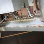
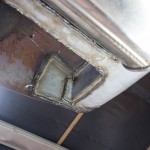
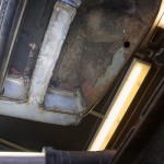
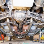
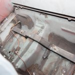
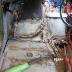
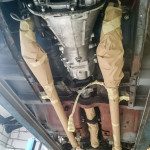
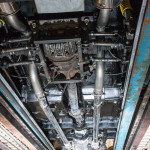
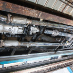
Additionally, some welding was tackled underneath.

And finally...

xzKTUdv.gif
 
Thanks for posting, really enjoyed reading it all. I restored a 105E when I was 14 with my grandfather, then we ran it for about 6 years, taking it to shows, then it was my daily driver when I passed my test. Great cars :)
 
First task was to remove the final bit of the chassis where it had started to go rotten - the rear cross member.

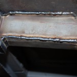
This involved cutting out the existing metal, and we decided to graft in a 50x50x3mm box section - which will be way stronger than the original box section. I may well add a jacking point/towing eye to this in the future. This was grafted onto the existing chassis legs (which are no longer load bearing due to the changes in suspension), and brought round to meet up with the original rear panel.


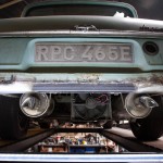
With the rear valance back in place - no visual differences from the rear.


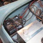
Moving forwards, the items that live in the boot are secured down - the battery is tied down, the straps for the fuel tank are secured to the floor, the vacuum tank for the servos is secured (you can just see a shiny strap in the first photo) and the charge cooler pump/reservoir are secured, as is the charcoal canister which prevents petrol fumes from being smelt via the tank breather.


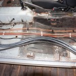
Moving forward again, and into the car this time. A new transmission tunnel top was fabricated and welded into place, to cover the 200SX gearbox. Additionally, all the fuel and brake pipes, as well as the main battery cable which run through the car were secured into place. The chargecooler pipes and vacuum pipe for the vacuum tank still need to be secured in their final positions once I get some suitable clips of the correct size for them.
 
So, I've concluded that I suck at taking photos and keeping this updated!

I've had a couple of trips to my dad's since the last update, and have failed to take any photos!

The first trip involved removing the engine/gearbox, and sorting out a couple of small oil leaks, which came from the lack of gaskets on the turbo oil return pipes. Whilst the engine was out, a new sump pan was also fitted, to replace the corroded one that was on there.

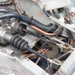
A little more tidying was done of fuel/vacuum pipes coming through the bulkhead, these now are plugged in on either side of the bulkhead to a small length of copper pipe which is soldered to the bulkhead. Quick to remove the pipes from inside or outside, and a water-tight way to get through the bulkhead.

Also, whilst the engine was out, the area we had cut away from the bulkhead to facilitate the water manifold and radiator hoses was looked at and mostly replaced, and we now have just a small removable panel to make and fit.


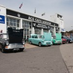
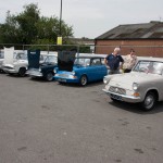
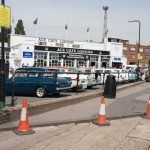
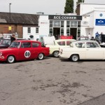
The second trip was more eventful, as we decided to take a day off from working on the car, to go and show it off at the annual Anglias At The Ace meet, organised by 105speed. The Friday evening was spent tidying up to make it somewhat "presentable" - it had a wipe down with a damp sponge and dried off with a towel, the passenger seat was re-fitted, the remaining cables under the dash were tidied with a few cable ties, and I even screwed in the glove box lid and ashtray/heater control panel!

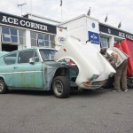
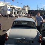
Saturday morning, we loaded up onto the trailer, and headed off for the Ace Cafe, my dad towing my Anglia, and me driving his, and arrived to a mostly empty car park, being about the 8th Anglia to arrive. We unloaded the trailer, and parked up, and awaited the rest of the arrivals.

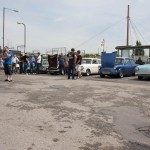
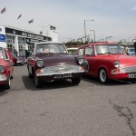
The day didn't disappoint, with 54 Anglias all together, and I had a great opportunity to speak to many people about the car.


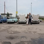
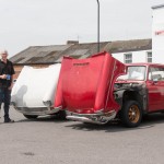
And our two cars, including my dad posing with his cup of coffee!


On our way back, we had a radiator blow out on the Shogun, which left us stranded at the side of the A406 for over 8 hours awaiting a truck to be provided that could recover the Shogun + trailer back home! So, that was quite a bad end to an otherwise great day!

I hope that normal service will resume next update, and I'll try to take some more photos!
 
Brakes, Suspension & Steering

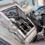
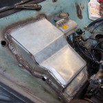
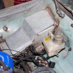
The first task tackled this time was to cover the pedals & master cylinders, to both make it water-tight, as well as add some strength back to the bulkhead where a little metal had been removed.

Therefore, a box was made up, with a removable lid to aid access, which covers this area. The clutch pipe was also re-routed inside the car, along with the brake pipes, moving it from its previous route which went down the bulkhead right next to the exhaust.


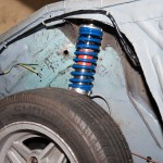
Next up was to fit a new set of front shocks & springs, which are now fully adjustable for ride height and damping rate.


When lowering the steering rack to allow the engine to fit in place, the steering geometry was modified from standard, by lowering the rack, "bump steer" was introduced - this is where the wheel as it moves up/down, also rotates as though it is being steered.

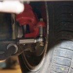
In order to overcome the bump steer that was introduced by the need to move the steering rack, it was necessary to move the mounting of the track rod end downwards, to match the downwards move of the steering rack.

This is accomplished by use of a long high tensile suspension bolt, suitable spacers, a rose joint and a length of hexagonal bar, with the correct threads tapped.


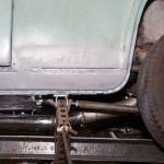
Moving underneath the car, the remaining chassis outrigger/jacking point was replaced - not with capabilities for the standard jack, but instead utilising some box section, which will give a perfect location for a more commonly available scissor jack, like is found with more modern cars.


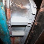
Additionally, the rear end of the driver's side sills were finished, which mostly concludes the remaining structural welding that was required underneath.
 
Great news everyone! The Dacia Sandero won't be on the Ford Anglia 105E Owners Club stand in hall 18 at the Lancaster Insurance Classic Motor Show at the NEC on 14-16th November!

But, my car will be!!

A few weeks ago I took a call from the club's events organisers, looking for a modified vehicle to show off on the stand, and have asked me to take mine.

So, amongst other things that need doing, we have been tidying up some things to get it into a transportable and "presentable" state.

This involves such tasks as...

Fitting of a new windscreen rubber:


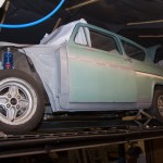
Some quick & unpolished grinding back of rough welds, filling of holes in the doors, and temporary rust protection of exposed metal with zinc primer:


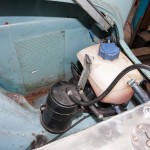
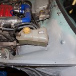
Making up a bracket to hold the coolant expansion tank (and more zinc primer):


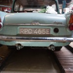
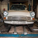
Fitting of the front bumper, and number plate:


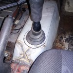
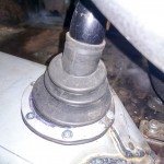
Fitting a gear lever gaiter:


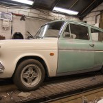
So, it's basically ready to be driven onto the trailer, unloaded and parked up on the stand. So, if you're visiting the show, come along to hall 18 and take a look in person!

 
Last edited:
First off, I know it's been a few months since any updates - I've not fallen off the face of the planet! The weekends have just fallen quite badly - with the likes of Christmas and other events meaning that time spent on the car has been reduced.

Some of this time has been spent in re-wiring the engine (again) - this time, using quick-release connectors, which will be located in a much better place than they currently are. The current connectors are all tucked down between the engine and the bulkhead, and have prevented us from making up the panel to seal off the bulkhead again.

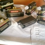
These are the connectors I'm now using - have worked out (after buying them) that 2x 20 pin connectors is enough to do all of the engine wiring (but no harm in having some extras)


It had always been a plan of mine to have fully independent suspension on the back of the car, because it allows the greatest amount of adjustment, which will be critical to get the handling just how I want it.

However, my dad didn't initially want to go fully independent, and so we came to an agreement on the De-Dion setup. The plan then was to drive it around for a while, and then redesign the suspension later.

However, he has since changed his mind, and come round to my way of thinking, so we've now started to replace the De-Dion with fully independent - whilst still maintaining the majority of the work on the suspension we've already done.

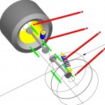
So, the plan is to replace the large, solid tube between the two hubs, and the panhard bar, with more links - we will need upper and lower, to prevent the wheels from folding in on themselves, or falling outwards (like the DeLorean from Back To The Future Part II). There will be 3 of these on either side - 1 top, 2 bottom, which will also allow for a control of toe.

The existing twin trailing arms will remain, and these will prevent the wheels from moving forwards/backwards, as well as preventing any rotational force applied by braking or acceleration.

The following diagram should hopefully explain this better, and this will be the basis of our design. (Red is the existing trailing arms, green will be the new arms we need to make)


Found on the SusProg3D site.


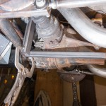
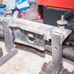
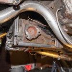
The first step is to add a frame around the diff, which will form the inner mounts of the suspension arms.


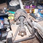
With the basic positioning sorted with it on the car, and the parts tacked together, we then removed the current axle, and put it all onto the bench for fully welding up all the parts for the frame that becomes part of the diff carrier.


Whilst it was still bolted to the car, we tacked on the lower brackets for the wheel end of the suspension arms - these will be fully welded on when we are perfectly happy with their position.


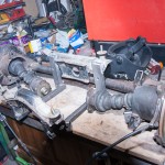
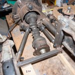
Putting it all together on the bench, we position the existing axle with the modified diff carrier, and begin to make up the suspension arms.


By doing it this way - until we are happy with the positioning, we don't have to cut through the De-Dion tube, so we could potentially bolt it back up to the car without affecting the current suspension setup! This is one of the reasons we prototype in the way we do - functional, usable, but not necessarily completed immediately - whilst yes, it took us some time to make the De-Dion axle, it allowed us to get it rolling under its own power, gave us the ability to position the diff, exhausts, trailing arms etc and build around them, but still give us the option to change things later - or, if we're happy with what we prototyped, we will go back to it and finish it off to a high standard.
 
The next task is to make up the suspension arms - 3 per side. 2 for the bottom, 1 for the top.

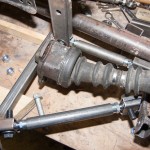
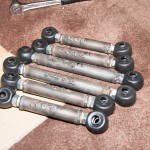
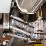
As with the trailing arms, these consist of a length of steel tube, threaded inserts, locking nuts, and rose joints. One rose joint is right hand threaded, the other is left hand threaded, and this allows fine adjustment of the length of the arm, without needing to remove anything from the car. Simply loosen the locking nuts, and rotate the tube to lengthen, or shorten, the arm as necessary.

This gives the ability to fully adjust every aspect of the suspension - the toe (whether the front of the wheels point inwards or outwards, and by how much), the camber (how far from vertical the wheels are), and the position within the arches.

We started by making the arms to the correct size needed to put the wheels in the same position as they are with the De-Dion. When looking at it on the car, I'd decided that the wheels were too close to each other, and ideally needed to fill the arches more - so basing the arm lengths on getting it as it current is, will allow adjustment outwards to where necessary (there's about 5cm of length adjustment on each arm, whilst still maintaining a suitable amount of thread within the insert - which gives up to 10cm overall width adjustment on each side... plenty, as it only needed to come out by about 2cm each side to really fill the arches)

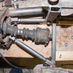
So, we made up the lower arms on the bench:


To get the correct length and position for the upper arms (avoiding the exhaust), we then began to transfer stuff to the car, firstly re-fitting the diff and carrier.

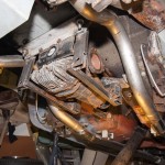
The next bit I forgot to photograph, so I'll try to explain what we did. We reattached the existing De-Dion axle, including the new lower arms, made up the top arms to length, and then removed it, and chopped the hubs off from each end of the De-Dion tube. This then gave us the hub units separately - our first step towards making them independent.

We needed to give a slight tweak to the exhaust pipes to give us clearance for the top arm - we could have curved it under the exhaust, but as the legendary Colin Chapman allegedly would have said, they then would have been "pre-failed". But, we've got enough capacity in the exhaust to be able to sacrifice a small amount of volume!


So, with the welded (and labelled) suspension arms:


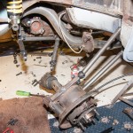
We began to attach each hub unit. First the two trailing arms:


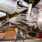
Then the remaining arms (as you can see, I was extremely useful here, and took it upon myself to take photos, rather than help hold the weight of the hub!)


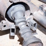
The rubber boots for the rose joints actually ended up causing us the most hassle - we'd used 25mm box section, which the bare joints slotted into perfectly. With the addition of the rubber boots, they just wouldn't fit right. So, we decided to use them slightly differently to how they are supposed to be used, and instead cut the end off them, and stretched them over the box section and over the nuts/bolts - just as water/dust tight, and much easier to fit!


So, with both sides attached, this is how it looks with full droop:

 
This update comes courtesy of my step-mum, who suggested that my dad booked a week off work to spend purely on the car! Thankfully, my girlfriend also thought it was a good idea, and so this is the culmination of a week's work! The last full week I had on the car (back in November 2011!), we made loads of progress - would this week be as productive? Read on to find out!


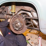
As the suspension mounts have been moved onto the diff carrier, the mounting points needed reinforcement. The rear mounts had already been reinforced, so we did the fronts, they now bolt through some nice heavy box section.


Where we had to cut away the bulkhead for the water pipes off the back of the engine, this needed replacing, so a new panel was made up. Originally we planned for this to be removable to gain access to the water pipes - but with the engine so simple to take out (less than an hour), there's really no point, so it's welded in for no loss in strength.


It was always to plan, once we'd proved that the brakes/clutch worked OK to replace the temporarily made push-rods with new ones, made from a single piece of metal, rather than the extended temporary ones.


Being a 1967 (and, of course, for safety), it needs seat belts in the front. A pair of inertia-reel seatbelts have been fitted, which are much better than the original fixed belts!


Having had the car running and driving for a while (only as far as in/out of the garage, and on/off the trailer), we noticed that the coolant level was dropping, and the oil level was increasing... so, the engine/gearbox came out, and it had a pair of new head gaskets, a set of 24 valve stem seals, new lower inlet manifold gaskets, and new injector seals/filters.


Whilst the engine was out (hopefully for the last time for a while!), the bare metal and welds were given some protection.


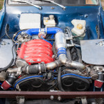
Not having enough of a single colour in the cupboard, we mixed together 4 different colours: Mitsubishi Fiji Blue pearlescent, Mitsubishi Twilight Blue metallic, Ford Java Blue metallic and Vauxhall Lagoon Blue metallic. So even the paint is a hybrid of various makes! (The flash makes it look a little lighter than it is in daylight - that's all the metallic/pearl bits catching the extra light from the flash)

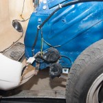
Meep meep! A pair of horns scavenged from a scrap BMW.


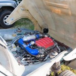
I mentioned before the new connectors for the engine - there's one of these on each side of the engine bay. So to remove the engine, we simply needed to unclip these two.


All the wiring inside, now completed, has been tidied up, tucked properly under the dash, and a panel was made up to house the boost gauge & various switches (hazard warning, heated front screen, clutch servo solenoid and launch control)


Then came the moment of truth - an MOT test! With everything put together, checked and double-checked, we took it for a fresh pair of eyes to give it a thorough check over. A nervous wait followed whilst the tester looked, prodded, pulled and poked at everything they usually look at, prod, tug and poke during an MOT test.

He then wandered through into the testing area, and presented a piece of white paper (I miss the days of coloured paper, where you at knew what the result was from across the room without having to read it!) - "Refusal of an MOT Test Certificate" was what this one was not titled! Instead, it said proudly at the top of the sheet "MOT Test Certificate" :D

Having sorted insurance a couple of hours earlier, I fired up the vehicle licencing page on my phone, and promptly taxed it and drove it back home!


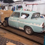
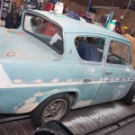
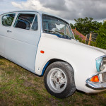
So - how far has it now been driven? Well... back home... where we then proceeded to start on tidying up the bodywork! Having seen the blue in the engine bay, we decided that, as there was some bare metal that still needed protection, to give the whole car a blow over with our newly created colour. All the bits of surface rust have been ground back and treated, the holes for the side trim (which isn't going back on) welded, ground back and filled over.


Next is to smooth back this filler, and give it a quick coat of primer & paint so it's all a single colour, and protected for now - until it comes off the road again in a few months to be stripped back to a bare shell to have a full, proper fix of bodywork and paint.
 
Prior to this weekend, it had been driven about 20 miles by my dad, and I was able to get down for a day, and in that time we have found, and had to sort the following teething issues:

Replace injectors - I fitted new filters to them, but in doing so, managed to get some dirt into some of them, which left them stuck open, pouring fuel into the engine!

Tweak the ECUs - the MAP-ECU appeared to lose some of its configuration, meaning that it was not actually giving a signal to the standard engine ECU for air flow! So the first 5 miles or so, it was running only on the "fail safe" fueling!

Replaced all the spark plugs, as it was missing under load.

Discovered that the tyres on the back are awful, as under power, it was pulling quite hard to the left, and to the right under deceleration. Swapping the rear tyres side to side improved it, so a new pair of tyres had been ordered and been fitted.

The PLX wideband O2 sensor control unit has failed, so it's not putting out the correct voltages on either the wideband output, nor the simulated narrowband output. This has been removed, and replaced with the stock narrowband sensor until I can afford a new wideband controller.


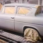
With the annual "Anglias At The Ace" happening the weekend just gone, and determined to get there, I went down and spent last Thursday night and Friday doing some more to make it ready. My dad had done some more filling & sanding, getting the car ready for paint. However, with life getting in the way, by Thursday it was only nearly ready for priming - so Thursday evening was spent finishing off the sanding back, and giving it a blow over with primer - which was finished at 12:15 on Friday morning!


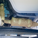
Friday morning I got up early, and spent the morning undersealing the car - if we were taking it on the road, the bits we'd previously welded and primed needed some better protection. So, after masking up all the bits I didn't want to get covered in underseal:


I covered both myself and the underneath of the car with underseal:


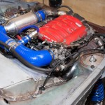
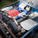
During the small amount of driving it had done, we noticed that the bonnet got VERY hot right above the turbos - so something was needed to reduce the heat transfer into the fibreglass. With a sheet of nice thick stainless steel, I made up some heat shields to cover the turbos, bolted onto the strut tops, so that the heat is transferred into the rest of the body.


With all that done, and just 25 miles on the odometer, it was time to firstly give the interior a good hoover out as it was covered in filler dust, and then take it out for a bit of a longer drive - firstly to see if the new tyres made a difference to the handling, secondly to see if the heatshields had made a difference before the "long" drive to the Ace Cafe, as well as to shake down anything else that we'd not picked up yet.


Given that I'd only driven it about a mile so far, I went out onto the road tentatively, and all felt good. As I started to become a little more confident, and the engine came up to temperature, I pushed it a little harder, until I was trying out some full-throttle runs. However, here is where I found an issue - it pulled great in 1st and 2nd all the way to the red line (no pulling to the left now the new tyres are on), but in 3rd and 4th, it got to just over 4000rpm and hit a rev limiter.

Came back, and got the laptop out and hooked it up to the ECUs to check the configuration. Nothing jumped out at me, so went out for another drive to save some log files for looking at later. There was also a small "chirping" coming from the back, which was related to road speed, that disappeared when lifting the handbrake slightly. Got it back home with the odometer now on a huge 49 miles!

I did find when looking through the logs that the original Mitsubishi ECU thought that I was doing over 400km/h - I certainly wasn't doing that!! I then remembered that the speed limiter on the ECU can't be removed, but it can be increased to 255 MPH - which is 410km/h!

So, with it being late on Friday, on Saturday morning got out early, cut the speed sensor signal to the ECU, and removed the rear wheels to back off the handbrake slightly.

With that done and back on the ground, we set off for our drive to the Ace. As this was the furthest from my dad's post code it has yet to be driven, we decided it safe for my dad to follow me in his Shogun with a trailer and a boot full of tools - just in case anything was to go wrong or not feel right, we could simply load it up, and deal with it later.

Heading off down the road, first I noticed that there was no more chirping from the back end. Getting onto the dual carriageway, I gave it full throttle in 3rd, and it revved straight past 4000rpm and to the redline - so it obviously was the engine ECU engaging the speed limiter at 4000rpm.

I had to pull over about half an hour and 25 miles after leaving home, however. As dad pulled over behind me, he gets out the Shogun with a worried look on his face as I walk towards him. "Can I have the duct tape, please?" I ask. "The chrome surrounds for the heater controls, and the ashtray are rattling, and it's annoying me", I add.

After taping up the rattling trim, the rest of the journey to the Ace was completely uneventful.


Another great day, met and chatted to plenty of lovely people, and saw 49 other lovely Anglias!

Then I drove it back home without any more issues, pulling up back at my dads with 210 miles on the clock. On a run, the engine coolant temperature gets a little higher than I'd like it to be, so (as was always expected) a better radiator is required for more serious running - but it'll sit happily at 70mph without overheating as it currently is.


It's only running at about 6psi of boost at the moment (I'm hoping I can get around 14psi out of it), so it's not quite as quick as it could be, but... even with that, it's rather quick! Using the timers built into the gauges, and still not *really* pushing it too hard yet, it's given so far a <7 second 0-60, and under 17s quarter mile. Just need to get it tuned right, get the launch control set up, and get it to a drag strip to see what it can really do!


So, err, how does a 5.9 second 0-60 sound?


That's the best my dad's got so far, and that's without getting it tuned properly, upping the boost or setting up the launch control!


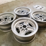
While he has been busy having fun with it (rather than painting it), I have been doing a quick refurb on a spare set of wheels.

 
Back
Top Bottom