@pc-guy and
Surveyor. Thanks for the replies however, and obviously it's my fault for not explaining properly, you're both telling my stuff i already knew, so I'll try to make my question make more sense.
")
So a standard 8pin connector has 3 power pins (+&- for a total of 6) and 2x sense pins, when plugged into the adaptor each of those get reduced to single wires and when all four are plugged in you've basically got 4 power wires (+&- for a total of 8) and 4 sense wires. Essentially we connect each 8 pin PCIe connector to a single wire pair and then connect those 4 wire pairs (4x8 +&-) to 12 pins, so why not just connect those 4 wire pairs (plus the sense wires) to another 8pin PCIe connector with the sense wires connected to the sense connector.
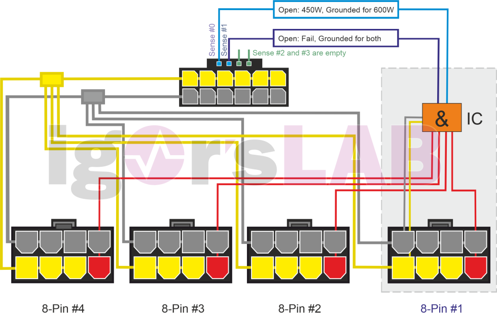
E.g Using the lower image you posted from Igor,
pc-guy, the yellow and grey boxes to the left of the 12pin have 4 wires going into them, one from each of the 4 x 8 pin PCIe connectors (and that's what the actual images show) so why not have a 8pin PCIe connector where those yellow and grey boxes are, why terminate 4 wire pairs (8 in total) on 12 pins, why not just terminate them on 8 pins.