

Associate
- Joined
- 1 Dec 2009
- Posts
- 367
- Location
- Bedfordshire
First time I have seen this thread, totally awsome build mate. A definate subscription! ")
 Curious to see how well it does compared to more commonly seen full towers (TJ07, V2000, 800D etc)
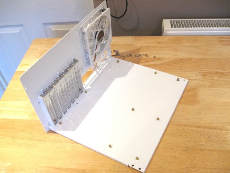
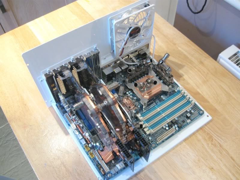
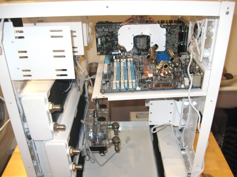
Good to see it finally getting some hardware in there!! See what you mean about the mobo tray though, could definately do with some sort of support under it.
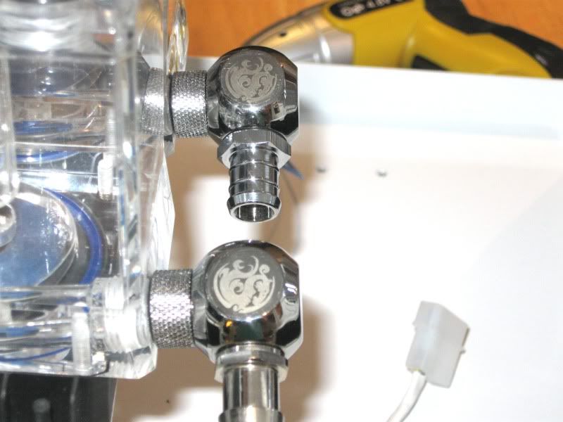
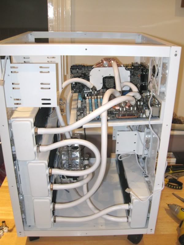
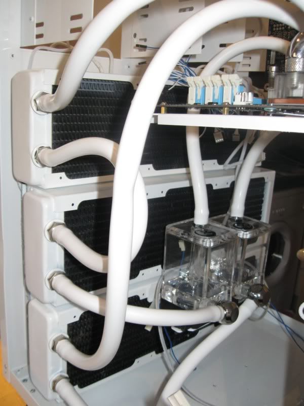
Do you have any angled bitspower fittings left? Most of the loops look good, but just thinking you could get the U shaped piece between the 2 front rads looking a bit tidier, its the only bit which is letting it down in my opinion. Other than that its looking stunning!

")