Cool, I'll have a look. If you're going to the trouble, surely 'fancy' is the only way to go, no?!
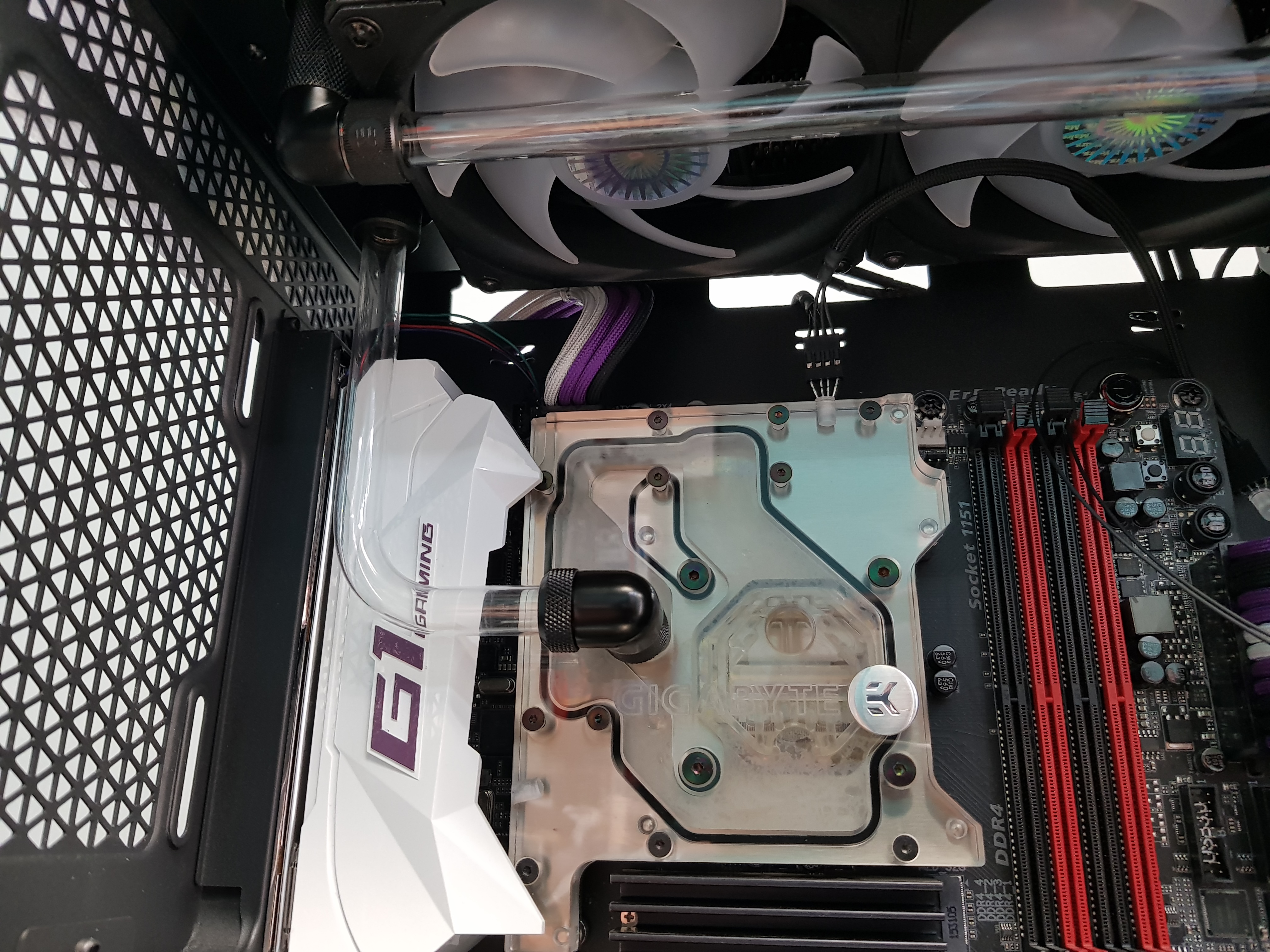
In the meantime, I started wiring the CPU-GPU ARGB LED chain. Only the CPU pair so far as until I disable a PC, the GPU isn't there so I don't know the length of the wire...hence the trailing pair left.
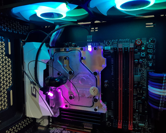
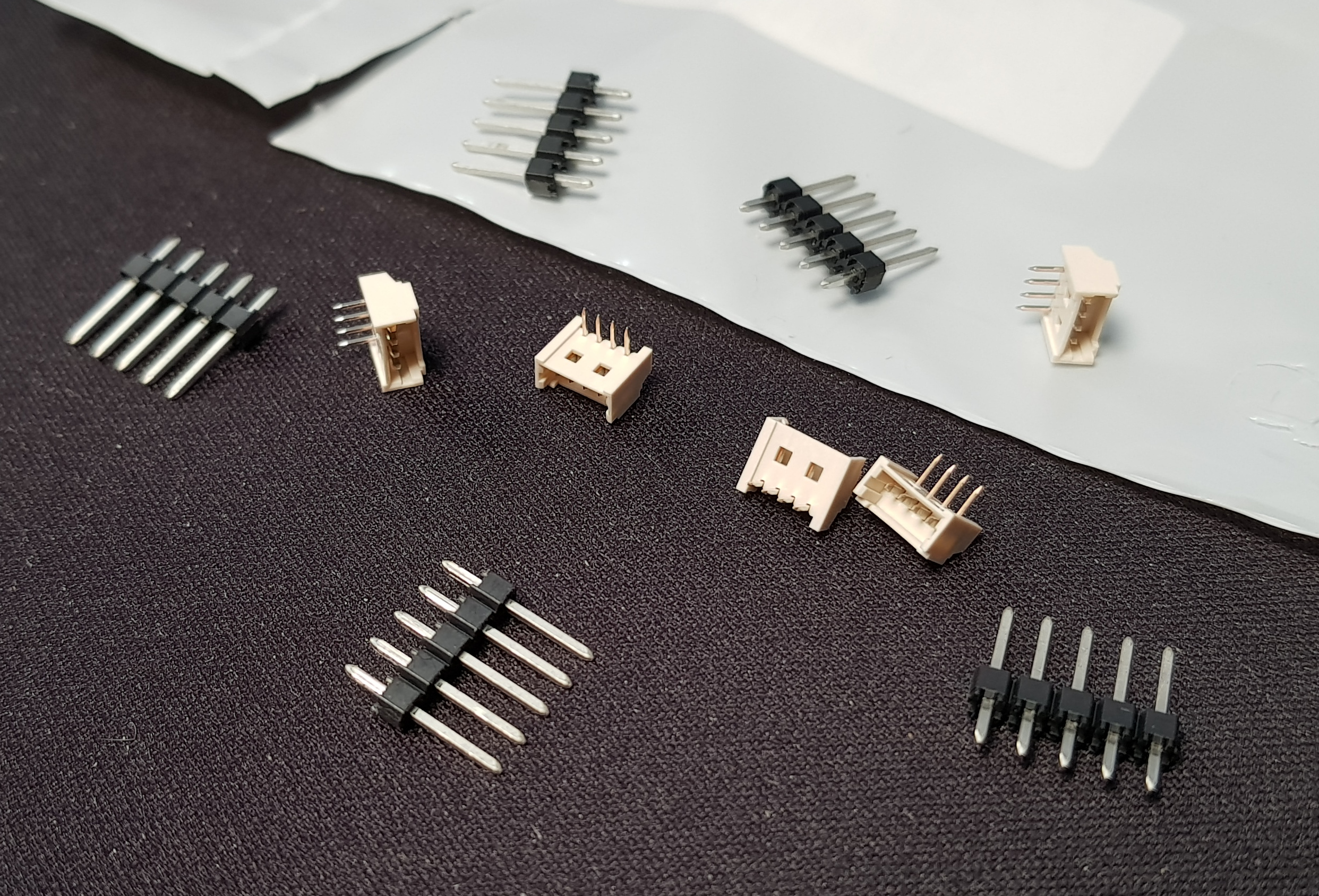
These are 5mm dome type WS2812b addressable RGB LEDs run directly from a Farbwerk 360. It may not be necessary to make the actual LEDs pluggable but I did it for my non-addressable RGB LEDs when I replaced them as an easy way of replacing them if they fail again. This way I guarantee they won't ever fail
Edit: Obviously when fitted properly the LEDs will be bent at 90° so the connector lies flat against the block and the wiring will be routed under the cowl at the back so it's out of sight....just no point doing any of that until the chain is complete.
In the meantime, I started wiring the CPU-GPU ARGB LED chain. Only the CPU pair so far as until I disable a PC, the GPU isn't there so I don't know the length of the wire...hence the trailing pair left.

These are 5mm dome type WS2812b addressable RGB LEDs run directly from a Farbwerk 360. It may not be necessary to make the actual LEDs pluggable but I did it for my non-addressable RGB LEDs when I replaced them as an easy way of replacing them if they fail again. This way I guarantee they won't ever fail
Edit: Obviously when fitted properly the LEDs will be bent at 90° so the connector lies flat against the block and the wiring will be routed under the cowl at the back so it's out of sight....just no point doing any of that until the chain is complete.
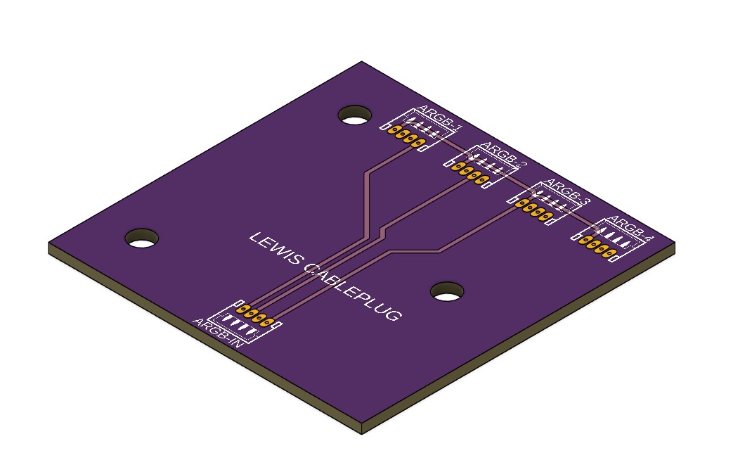
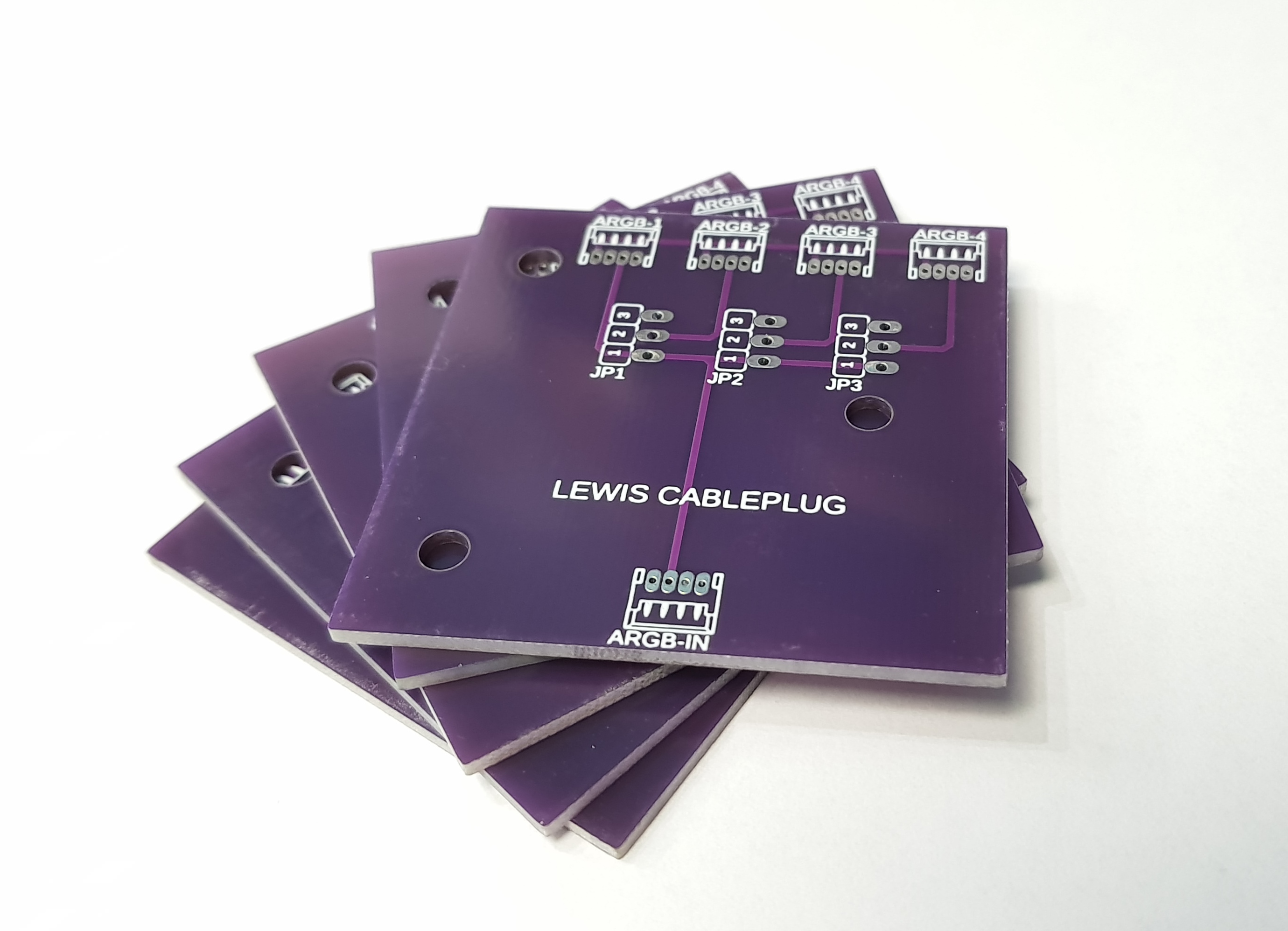
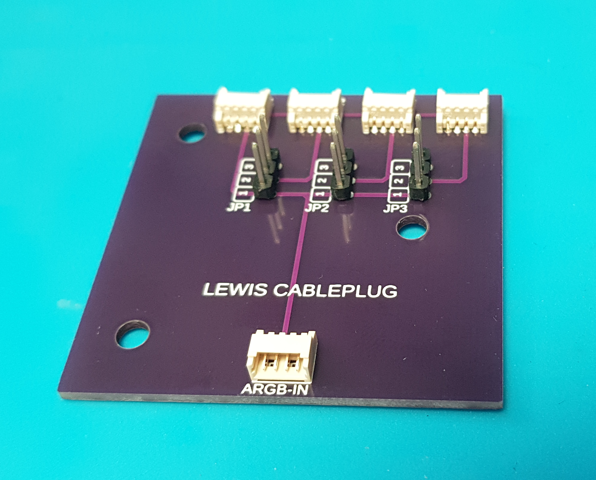
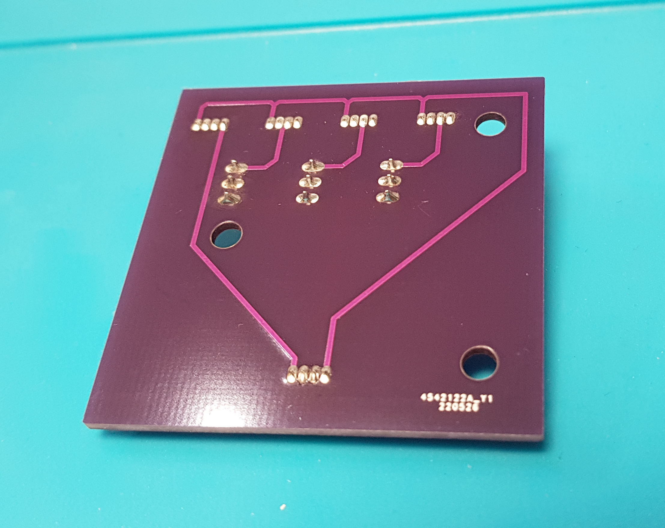
 Was looking at JLCPCB just because they have the option for cheaper shipping at £3.10 for 2-week shipping.
 Order's in, now to get the connectors ordered to solder onto the thing!
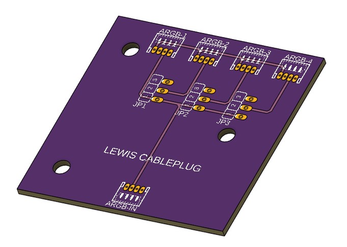
")