Ronski's Solar & battery DIY build with whole house backup

The new consumer unit is just for the garage, the existing fuse box dated from cira 1974 :D

The earth cable running left is to a spike, this is solely for when running off grid, the inverter will switch to this if the grid fails. This is the only bit I'm not keen on, it could have been installed nearer to the other stuff, then the spike/cabling outside would be less visible.

What would you like to see pictures of?

>> We might require the addition of a 100a MCB, in theory the inverter can pass through 100a and add an additional 34a/8kw which would exceed the cabling and rating of the CU.
Neat. The house end would be good to see?

Interesting re the earthing, the guidance I've read all says the spike can be bonded to your incoming earth (/neutral for TNC-S) whether or not you're running on backup mode. Its just the idsconnect of the L&N supply and the creation of earth/neutral bond that has to be made at the inverter on backup mode. If otherwise would be interested to hear. https://engx.theiet.org/f/wiring-and-regulations/25149/battery-backup-earthing---pme-supply/109663

A 100amp service fuse may be better... that will give you leaway to pull more than 100a for short periods being more tolerant of temporary high loads and is the same as every other house. Cheaper too.
 
Last edited:
Neat. The house end would be good to see?

Interesting re the earthing, the guidance I've read all says the spike can be bonded to your incoming earth (/neutral for TNC-S) whether or not you're running on backup mode. Its just the idsconnect of the L&N supply and the creation of earth/neutral bond that has to be made at the inverter on backup mode. If otherwise would be interested to hear. https://engx.theiet.org/f/wiring-and-regulations/25149/battery-backup-earthing---pme-supply/109663

A 100amp service fuse may be better... that will give you leaway to pull more than 100a for short periods being more tolerant of temporary high loads and is the same as every other house. Cheaper too.
@SBo:

Thats quite interesting, done a little smurfing and found this.. I am no sparky but reading this then you should be be able to connect the earth spike to the incoming DNO earth point.. as you say the L-N will be taken care of by the Ground_Relay in the inverter - (look at Figure 9-10):


@ron:
If I may ask, how is your earth spike setup/connected - end to end ? - BTW, congratulation of the setup, Top Notch fella, am impressed Sir !!
 
Can i ask what yuo may use to do that?? as i want the same sort of monitoring, but not sure what to use....

At the moment i am using an efergy sensor, transmitter and monitor....but its not online data and there's no way of getting that data from the monitor ( unless you buy the home hub) which is not in stock currently anywhere lol

Few ways to do this but full hack would be a pi or similar device using a hat, ct sensor. You can also buy specific addons like I can get an extension to the eddi diverter that will allow less flexibility but with HA could likely read the data.
 
Neat. The house end would be good to see?

Interesting re the earthing, the guidance I've read all says the spike can be bonded to your incoming earth (/neutral for TNC-S) whether or not you're running on backup mode. Its just the idsconnect of the L&N supply and the creation of earth/neutral bond that has to be made at the inverter on backup mode. If otherwise would be interested to hear. https://engx.theiet.org/f/wiring-and-regulations/25149/battery-backup-earthing---pme-supply/109663

A 100amp service fuse may be better... that will give you leaway to pull more than 100a for short periods being more tolerant of temporary high loads and is the same as every other house. Cheaper too.

I'll get a picture tomorrow for you, although that side is not yet finished, electrician needs to come back and change the CU, they said it needs to be up to date as they are altering the supply to it, so I'm having an up to date one with RCBO's fitted.

The electrician did say IIRC that the earth spike can be connected to the DNO earth point, I'm not actually totally sure which way they did - I'll have a look tomorrow.

If I may ask, how is your earth spike setup/connected - end to end ? - BTW, congratulation of the setup, Top Notch fella, am impressed Sir !!

As per above, I'll need to check exactly how they connected it.
 
I'll get a picture tomorrow for you, although that side is not yet finished, electrician needs to come back and change the CU, they said it needs to be up to date as they are altering the supply to it, so I'm having an up to date one with RCBO's fitted.

The electrician did say IIRC that the earth spike can be connected to the DNO earth point, I'm not actually totally sure which way they did - I'll have a look tomorrow.


As per above, I'll need to check exactly how they connected it.
Thanks Ron
 
Some pictures for you, note its not totally completed, new consumer unit to be fitted, labelling and some tidying up to be done. Covers removed for taking the picture.

House wiring, by consumer unit. You can probably work it out without me explaining.

House-Wiring.jpg


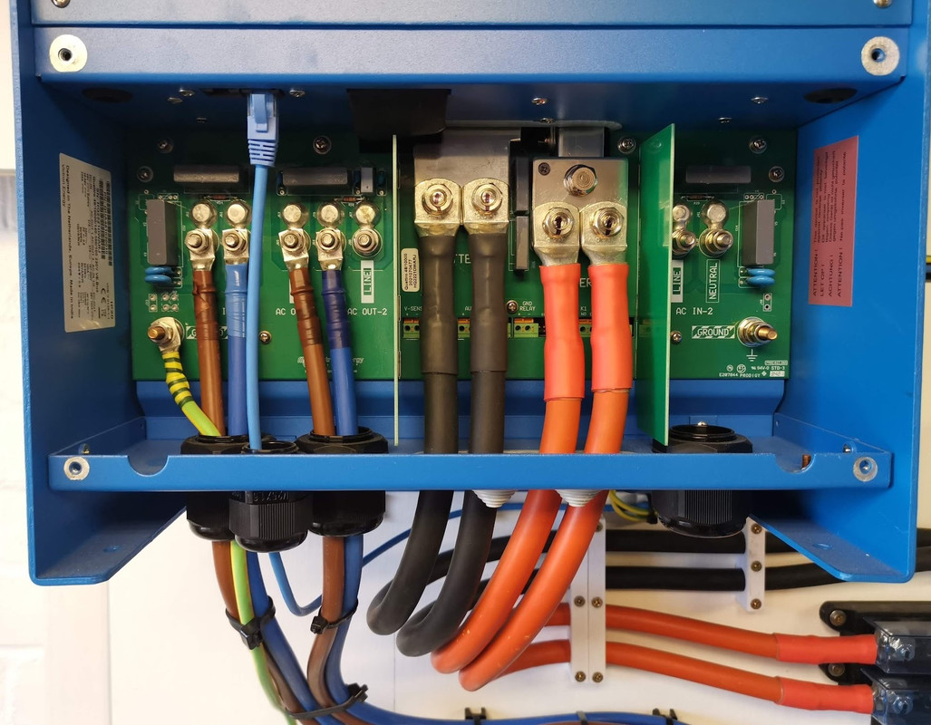
Inverter wiring. Grid comes in on AC in 1, which is on the left, supply to consumer units goes out on AC out 1.

Inverter-Wiring.jpg


Switch gear and earthing. If you follow the earths, you can see that they are all linked together with the ground spike. Spare 25mm SWA is just a bit I had left over, so I put it in the ground and ran it back to the house wall, where in the future it could be used to supply a heat pump.

Switch-Gear-Wiring.jpg


Emergency by pass switch gear/isolators (lockable)

If the inverter is turned off, the house loses power, so if there was ever a problem with the inverter, or it needed to be worked on, it can easily be bypassed, its just two change over switches linked together.

Switch-Gear.jpg


Some of you may have noticed the fused switch in the first picture was turned off, and this is the grid supply via the meter and DNO fuse, you have to turn it off to take the cover off, so whilst I removed the covers, took the pictures and put them back on we were running completely off grid.

So what happened you may ask? Well, pretty much nothing at first, the power stayed on, the server stayed running.

Then I noticed the SolarEdge PV had stopped generating, but I still had power, so in theory it should have been generating. Checking the frequency there was a small increase to 51.6Hz, not sure how long this lasted as the graphs are only in minute intervals, but the graph shows it was no longer than two minutes, then the frequency settled back to 50Hz and the SolarEdge PV started generating again. This proves that frequency shifting does stop the SolarEdge system from generating, this is very important.

In the extremely rare situation of the grid being off, the batteries being full, and the solar generating, the excess power needs to go somewhere, and that somewhere is the batteries, but eventually the BMS will shut off charging to protect the cells, also at some point the inverter will shut down. To prevent this the system is set to shift the frequency (this can only be done off grid) and shifting the frequency will shut down the SolarEdge PV. I do need to test this actually works, I believe it should happen at 95% state of charge, but now I do at least know the SolarEdge System does shut down. The Victron MPPT's will throttle back when the DC battery voltage reaches a set point, so these arn't an issue, just AC connected PV.

The other thing I noticed is that my server UPS went onto battery, probably due to the frequency increase, so need to check the settings there.

Best I get on with some work.
 
Last edited:
  • Like
Reactions: SBo
I guess there is a lag on going off-grid as well, it has to notice it's lost the grid and there will be some sort of response time rather than instant?

Not an immediate concern as well but I'd like to see roughly what the cost was and what the final result looks like in terms of headline extra stuff (i.e. extra X kWp, battery storage for Y kWH, off-grid capability etc).
 
Yep, got an alarm on my phone pretty instantaneously, which I would get any where in the world so long as both ends have a data connection.

Alarms.jpg


I will add up the costs, but it is going to come in very expensive, but still less than some quotes I've seen on here for far less capable systems. One benefit of it taking so long is I've actually been able to pay for it with only using disposable income, and some from the Mrs.

I now have 8.74kw of solar, an addition of 4.74kw, 14.5kWh battery, but that is if I used the full capacity from 3.65v down to 2.5v, I'm going to be using the 2.9 to 3.45v range, but capacity drops off very quickly either side of those voltages. I will add a second battery, as the system really needs it, and the extra capacity will be useful.
 
Yes with so much generation potential and the buffer for lower end off-grid options, you'll probably need the additional capacity. Whilst not cheap, guessing it's far easier to add that and not have lots of extra costs with all the prep you've done here.

All in all this will be a pretty epic system :)
 
Last edited:
@HungryHippos think I misread your previous reply, there is no real lag when going off grid, Victron state the following.

The main output has no-break functionality. In the event of a grid failure, or shore or generator power being disconnected, the Quattro takes over the supply to the connected loads. This happens so fast (less than 20 milliseconds) that computers and other electronic equipment will continue to operate without disruption.

The Quattro can charge the battery at up to 140A (48v DC side) from the grid, great for those short periods of cheap rate electric. At 09:50 this morning I was seeing 86A going in to the battery just from PV. 140 amps is 0.5C which stresses the cells more, having two batteries would half the current to each, same goes with discharge, the Quattro can pull 160A at full capacity. Spreading this load across two batteries will hopefully mean they last much longer.
 
I still kind of hope that one day my G1 inverter dies (whilst still in warranty) and they have to give me a G2 one! :)

Charge and Discharge rates are important, but it's not the end of the world, 2.6kW is my max and it's workable if I do things in sequence.
 
Was just looking at the VRM (its rather addictive whilst its all so new), and AC loads went to over 6000w, grid went up a little to about 240w then immediately settled down to around zero. Mrs had just put the oven and kettle on at the same time, apart from the slight fluctuation it was all supplied via the inverter :D
 
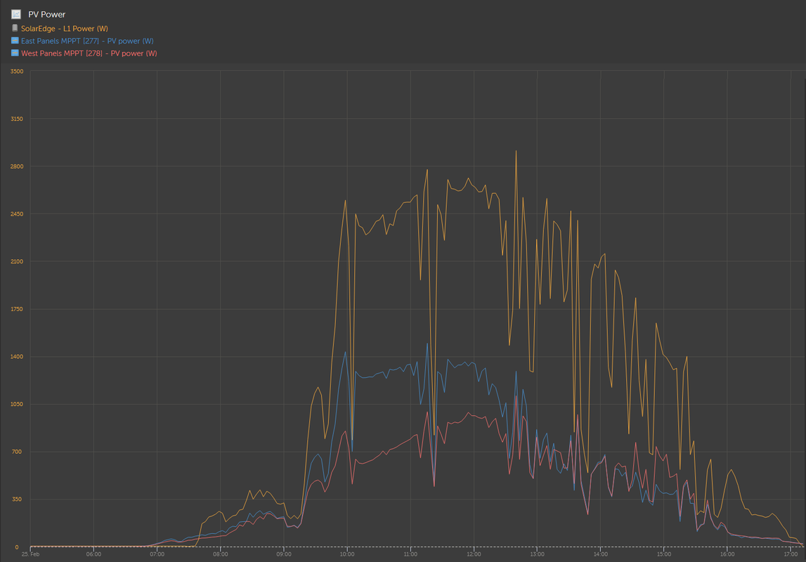
@katie279 I noticed today that the PV Power graph had 3 Y axis scales, which is why the three arrays seemed to be very close together on the graph, I've now set it to a fixed scale for all three arrays.

SolarEdge system produced 13.07kWh
East Garage Array produced 5.65kWh
West garage array produced 4.42kWh

So on a sunny day but still some clouding the 4kw SolarEdge system beat the 4.74Kw Victron system by 3kWh, on a cloudy overcast day the Victron system does better.

PV-Power-25-02-2023.png
 
Great to see you having fun with it now it is nearly finished. Looking like my new system will go in April time, but nothing set in stone yet. Could you drop me a message as to where you got your ZJ-BENY stuff please?
 
Back
Top Bottom