Does it really matter which DP port I use, chances are I'll be faffing for a while yet, missus is off out shortly, my DP extension right angle has just turned up and so has my standoff kit, shes going to Ikea so I should get about 3 hours to play..
You are using an out of date browser. It may not display this or other websites correctly.
You should upgrade or use an alternative browser.
You should upgrade or use an alternative browser.
SSUPD MeshLicious (from the makers of the FormD T1)
- Thread starter Pocket10s
- Start date
More options
Thread starter's postsSoldato
- Joined
- 8 Jan 2003
- Posts
- 3,803
- Location
- Scotland
After stripping down my PC on Monday and finding out I needed a couple of different fittings as the EK Torque fittings were too big for the IceMan reservoir (I knew this already and bought an extender but stupidly bought an EK Torque extender!), I had to wait until yesterday to start putting it all back together. I then had a drama last night where I thought I had stripped the threads when attaching the pump to the reservoir as I had a leak but it turned out it was the drain plug I had fitted that was leaking (the irony!).
Anyway, she's now up and running. Haven't done any temp testing yet as I've only just got it up and running with AquaSuite setup to control fan curves based on water temp.
As my GPU is quite big (PowerColor Red Devil 6900 XT), I had to move the GPU side to the 4 slot position meaning I could no longer do that stand-off trick for cable management, hence the rats nest of cables!
Case has now been purchased!
I have a NVME on the back of the motherboard (Western Digital Black SN750 2TB - no heatsink). Do the default standoffs that come with the case provide enough clearance for a NVME to be present and only heat is the concern? Or will additional standoffs be required regardless?
I have a NZXT Kraken x52 240, does anybody by any chance know what the max standoff size allowed for this AIO?
And in terms of standoffs is it the M3 that is required? Any brand fine? best getting brass? or are the black nylons durable enough to hold the weight?
Thanks in advance
Soldato
- Joined
- 8 Jan 2003
- Posts
- 3,803
- Location
- Scotland
Case has now been purchased!
I have a NVME on the back of the motherboard (Western Digital Black SN750 2TB - no heatsink). Do the default standoffs that come with the case provide enough clearance for a NVME to be present and only heat is the concern? Or will additional standoffs be required regardless?
I have a NZXT Kraken x52 240, does anybody by any chance know what the max standoff size allowed for this AIO?
And in terms of standoffs is it the M3 that is required? Any brand fine? best getting brass? or are the black nylons durable enough to hold the weight?
Thanks in advance
My Nvme slots straight into the back of the motherboard, nothing additional required.
I guess the brass stand-offs will be stronger but I used the black nylon ones and they worked fine, I was just a bit more careful when putting strain on the motherboard. Just the standard motherboard stand-offs will fit, not sure if those are M3.
I used the black nylon ones, the brass were out of stock when I ordered.
So far I have also ordered a short DP angled cable.
I also use the different PSU bracket to create a gap behind and under the PSU itself, airflow and all that..
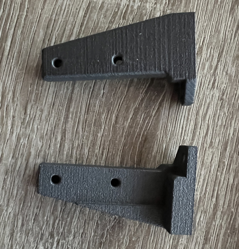
I'll be doing some sort of GPU bracket to move it a bit further towards the side of the case as having the 3080FE means that fan on the back, useful for moving air over the nvme I have on the back of the board, not so good for heat, so I'll be doing some sort of 3d printed duct so that the fan can suck air in from the back where the removable GPU slots are.
I'll also 3d print a small back plate for the hole where the cables come out as the extension I bought has screw holes in it so I can mount using those.
I'll also most likely be adding feet to air airflow under the case.
How far out to they push the GPU?
I'm going to get some but was thinking of designing something a bit more universal depending on what sort of riser standoff people were using, I will be doing to riser standoff with the brass stand offs though not the nylon ones I've used for the motherboard simply because I suspect the GPU with the cable in the bottom will get moved more than the motherboard will.
I'm going to get some but was thinking of designing something a bit more universal depending on what sort of riser standoff people were using, I will be doing to riser standoff with the brass stand offs though not the nylon ones I've used for the motherboard simply because I suspect the GPU with the cable in the bottom will get moved more than the motherboard will.
Does it really matter which DP port I use, chances are I'll be faffing for a while yet, missus is off out shortly, my DP extension right angle has just turned up and so has my standoff kit, shes going to Ikea so I should get about 3 hours to play..
The right angle of the Display Port cable does matter! I ended up getting the wrong one! Having to rest the case on the stand off box I bought at the moment so I can use the standard Display Port cable.
Anybody actually buy the SSUPD right angled display port cable from OCUK? (at £25 I suspect not), any pictures of this?
My Dell Monitor does not support HDMI above 60Hz I don't think, the right angled HDMI included with the case would not detect above 60Hz at 1440P anyway (or even at 1080P) (HDMI does not support gsync either?)
I'm considering whether to buy the correct right angled Display Port or some feet.
I'd quite like the feet but I don't really like all of the custom ones on etsy. I like the horizontal SKI type feet idea on there but don't like how they are not flush to the front and back of the case, would also like to see them blocked out and not as tall.
Did the build yesterday, ended up with the NZXT logo on the X52 upside down though as it fitted better with the aesthetics of the tubes.
Shame about the red plastic cover of the PCI-E riser, strange they didn't ship that in black, can it be removed/changed?
Thanks in advance
The right angle of the Display Port cable does matter! I ended up getting the wrong one!
I wasn't on about the cable, I was on about the port on the card though..
I'm nearly finished with my Mechlicious now, it's taken a bit longer than I'd hoped but I've had so many changes of plans along the way, this is the first time I've got a mocked up loop in place so I know what finishing touches need doing.
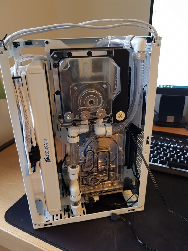
I've cut to length, re-sleeved and routed the fan cables. The RGB hub is located at the back of the case. I need to do the same for the RBG cables for the water block and resevoir. I've also got to sleeve the SATA power cable to the RGB hub because it's a bit of a mess at the minuite.
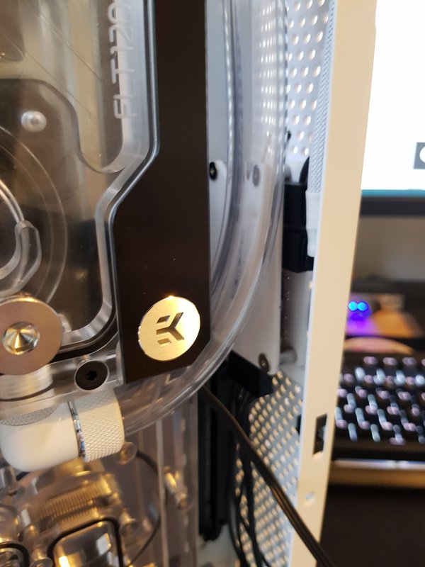
I need to cable tie some of the fan cables so they're a bit neater and don't interfere with the case side panel.
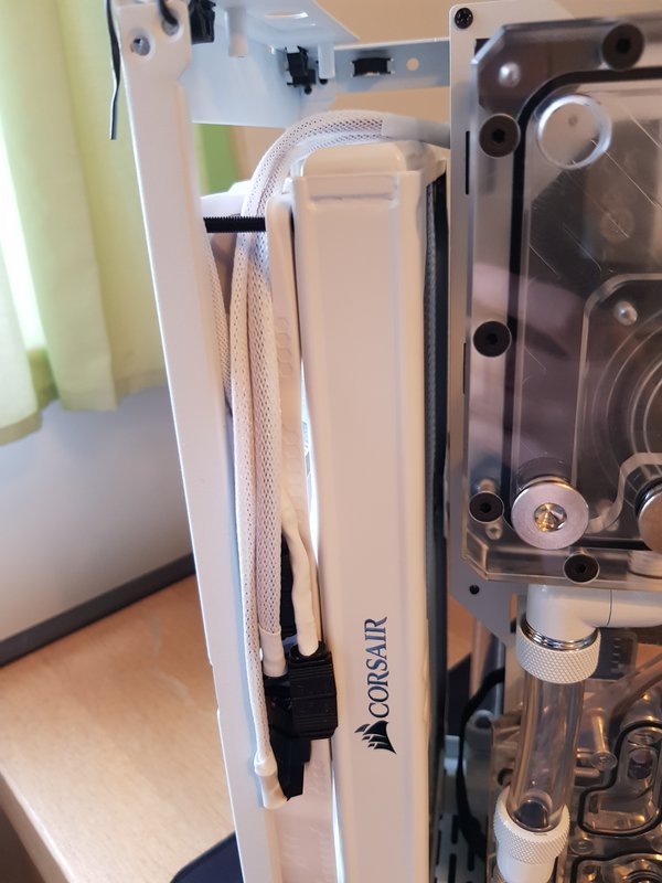
The inlet and outlet tubing from the GPU needs tweaking ever so slightly. I think where it comes out of the GPU and into the resvoir (the slightly longer tube) isn't as vertical as I'd like it to be. I'm going to add a spacer between the two 90° fittings to move them over towards the front of the case slightly which should make it look better.
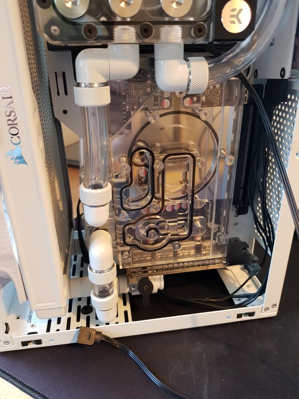
The motherboard and power supply are fitted and connected up to the loop. Due to the length of the PCI-E riser cable I was forced to mount the motherboard on the normal stand offs. Originally I had this mounted further away from the spine of the case on longer stand offs which gave more access behind the board but the riser cable wasn't long enough with a full size ATX PSU.
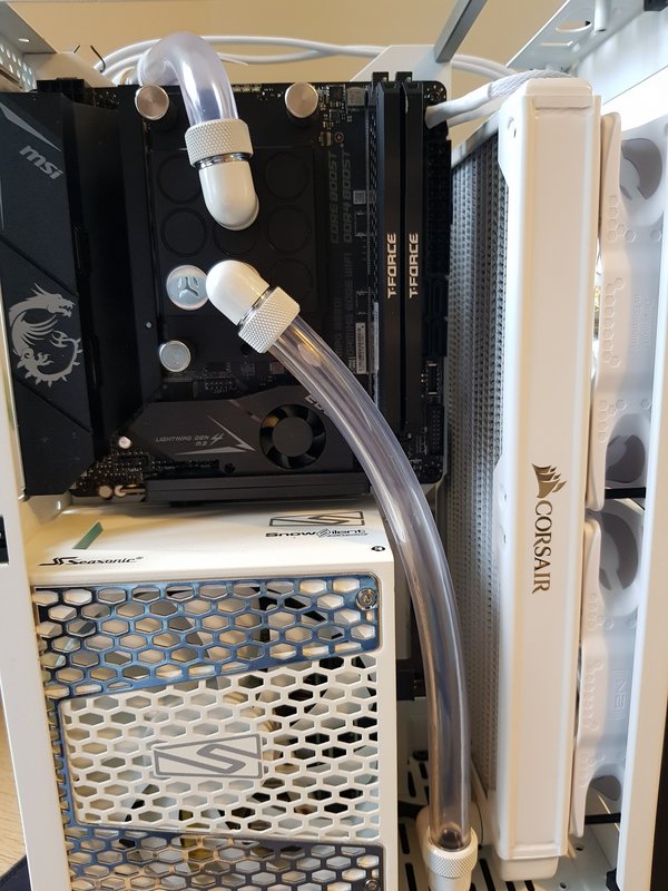
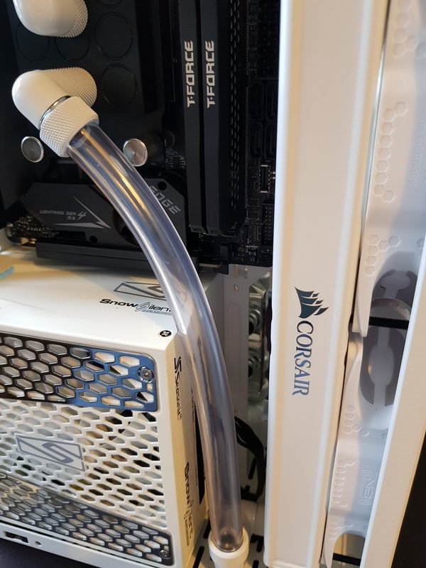
With the two 90° fittings attached to the radiator I've got plenty of room behind the tube here for cables to be plugged in. I'm awaiting on some custom length cables for the 12Pin GPU, 24Pin ATX and the 8Pin EPS cable. These should all fit in fine as I've routed the EPS cable behind the motherboard and over the top of of the spine of the case. The only real issue is going to be the oversized and ugly USB header cable. Why hasn't a low profile version of that monstrosity ever been made?
So all I'm left with is the following:
- Sleeve the SATA power cable for the RBG hub
- Sleeve the RGB cables for the GPU water block and resevoir
- Test the RBG in isolation connected to my other system
- Cut and route the RGB cable from the hub to the motherboard
- Leak test the loop
- Connect up the custom EPS, ATX and GPU cables when they arrive

I've cut to length, re-sleeved and routed the fan cables. The RGB hub is located at the back of the case. I need to do the same for the RBG cables for the water block and resevoir. I've also got to sleeve the SATA power cable to the RGB hub because it's a bit of a mess at the minuite.

I need to cable tie some of the fan cables so they're a bit neater and don't interfere with the case side panel.

The inlet and outlet tubing from the GPU needs tweaking ever so slightly. I think where it comes out of the GPU and into the resvoir (the slightly longer tube) isn't as vertical as I'd like it to be. I'm going to add a spacer between the two 90° fittings to move them over towards the front of the case slightly which should make it look better.

The motherboard and power supply are fitted and connected up to the loop. Due to the length of the PCI-E riser cable I was forced to mount the motherboard on the normal stand offs. Originally I had this mounted further away from the spine of the case on longer stand offs which gave more access behind the board but the riser cable wasn't long enough with a full size ATX PSU.

With the two 90° fittings attached to the radiator I've got plenty of room behind the tube here for cables to be plugged in. I'm awaiting on some custom length cables for the 12Pin GPU, 24Pin ATX and the 8Pin EPS cable. These should all fit in fine as I've routed the EPS cable behind the motherboard and over the top of of the spine of the case. The only real issue is going to be the oversized and ugly USB header cable. Why hasn't a low profile version of that monstrosity ever been made?

So all I'm left with is the following:
- Sleeve the SATA power cable for the RBG hub
- Sleeve the RGB cables for the GPU water block and resevoir
- Test the RBG in isolation connected to my other system
- Cut and route the RGB cable from the hub to the motherboard
- Leak test the loop
- Connect up the custom EPS, ATX and GPU cables when they arrive
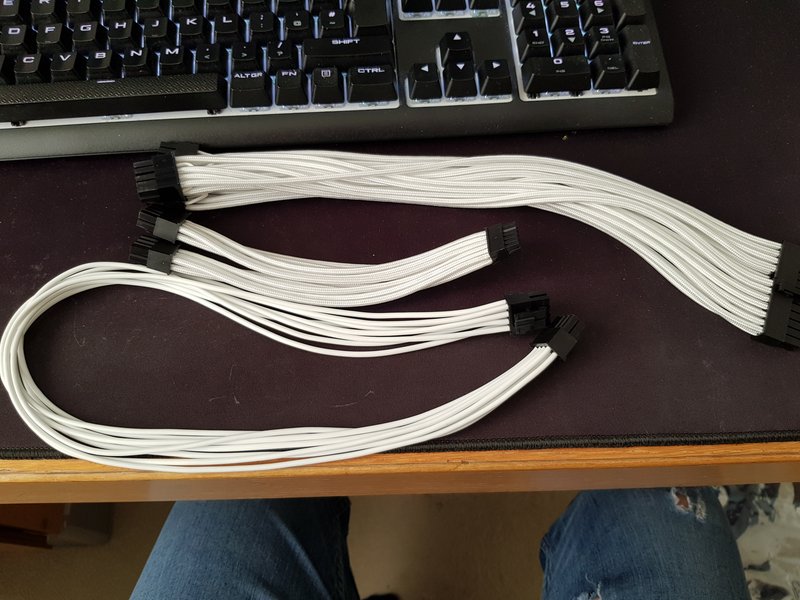
White sleeved custom length cables have turned up. Custom 27cm ATX cable, 15cm 12Pin GPU cable and 8Pin CPU cable. The 8Pin CPU power cable is paracord cable, which is really soft and easily manipulated. I'm hoping to route it behind the motherboard.
Should hopefully have the cabling finished this weekend ready for a proper leak test.
Soldato
- Joined
- 8 Jan 2003
- Posts
- 3,803
- Location
- Scotland
Finally got my build re-done over the weekend. I had switched the case to the 4 slot GPU layout as I was under the impression that using the Iceman reservoir with the case in 3 GPU slot mode blocked using the ports on the GPU. However after further research, it appears not to be the case. I also had some contamination in my loop after only 3 weeks so had to strip it anyway to clean the GPU block.
So changes made were;
A lot happier with it now that the cable clutter is reduced and the blocks are cleaner. I have a couple of outstanding issues.


So changes made were;
- switched the case to 3 slot GPU setup
- used the standoff mod for the motherboard
- switched the Nickel + Acetal EK block for the Nickel + Plexi block
- switched out the CPU side mesh panel for the dark tinted glass panel
- switched out the Gigabyte B550i motherboard for the Asus B550i ROG motherboard
- removed the Aquacomputer Quadro fan controller
A lot happier with it now that the cable clutter is reduced and the blocks are cleaner. I have a couple of outstanding issues.
- The front USB header on the case doesn't work. It did with my Gigabyte board so potentially an Asus board issue?
- Not sure why the GPU block RGB doesn't come on. The EK CPU block and the EK GPU block are both connected via an EK RGB splitter to the same RGB header on the motherboard. On another note, the PowerColor 6900XT GPU port lights are annoying and don't appear to be controllable.
Armoury crate, you're going to be introduced to the downside to Asus Mobos. It's a piece of software that has the Asus Aura Sync rgb controls in there. It is also buggy and doesn't play well with others.. see Corsair RGB ram.
open up Armoury crate, select Aura Sync and select and sync all devices you have connected /it detects and go from there
open up Armoury crate, select Aura Sync and select and sync all devices you have connected /it detects and go from there
Soldato
- Joined
- 8 Jan 2003
- Posts
- 3,803
- Location
- Scotland
Yeah, I'm aware of this "legendary" piece of software having tried to use it on a Gigabyte motherboard to get the RGB working on my Crucial RGB ram as that was unbelievably a suggested solution. Needles to say it didn't work and installed a load of crap! So I've not installed it this time around and use OpenRGB to control the RGB. It does detect the Asus motherboard RGB header and does allow my to control the colour of the EK CPU block and given the GPU block is off the same header via a splitter, I'm not sure why that's not working.Armoury crate, you're going to be introduced to the downside to Asus Mobos. It's a piece of software that has the Asus Aura Sync rgb controls in there. It is also buggy and doesn't play well with others.. see Corsair RGB ram.
open up Armoury crate, select Aura Sync and select and sync all devices you have connected /it detects and go from there
Associate
- Joined
- 4 Jun 2021
- Posts
- 475
- Location
- Yorkshire
Yeah, I'm aware of this "legendary" piece of software having tried to use it on a Gigabyte motherboard to get the RGB working on my Crucial RGB ram as that was unbelievably a suggested solution. Needles to say it didn't work and installed a load of crap! So I've not installed it this time around and use OpenRGB to control the RGB. It does detect the Asus motherboard RGB header and does allow my to control the colour of the EK CPU block and given the GPU block is off the same header via a splitter, I'm not sure why that's not working.
Does the EK Splitter just replicate the DRGB signal, or does it effectively daisy-chain them? If the latter, did you set the number of LEDs in the chain in OpenRGB to the sum of the number of LEDs in the two blocks?
Soldato
- Joined
- 8 Jan 2003
- Posts
- 3,803
- Location
- Scotland
Good shout actually. I did set the number of LEDs to the amount on the CPU block, not the totalDoes the EK Splitter just replicate the DRGB signal, or does it effectively daisy-chain them? If the latter, did you set the number of LEDs in the chain in OpenRGB to the sum of the number of LEDs in the two blocks?
 Now I need to change it but I can't recall where I found the setting!
Associate
- Joined
- 4 Jun 2021
- Posts
- 475
- Location
- Yorkshire
Good shout actually. I did set the number of LEDs to the amount on the CPU block, not the totalNow I need to change it but I can't recall where I found the setting!
On the devices tab, select the appropriate motherboard header under the zone drop down and click resize.
Soldato
- Joined
- 8 Jan 2003
- Posts
- 3,803
- Location
- Scotland
Nevermind, found it. That kinda worked. I increased it to 29 (20 on the CPU block, 9 on the GPU block). The EK logo on the inlet/outlet section is now lit but there are no LEDs on the plexi section lit.
Thanks though.
On the devices tab, select the appropriate motherboard header under the zone drop down and click resize.
Thanks though.
Last edited:
Soldato
- Joined
- 8 Jan 2003
- Posts
- 3,803
- Location
- Scotland
Just wondering if something has come loose. I did notice when I was setting up my card, the LED lead has two tiny connectors on it. One connected into another cable that has the standard D-RGB connector on the end, the other wasn't plugged into anything. For some reason I assumed that was some kind of spur to allow you to plug something into it. But on reflection, thats a stupid idea as its a tiny connector. I bet that plugs into something in the card. If it has come loose then it was like that from the factory. I ordered direct from EK and it arrived like that.
Having just spent all day yesterday rebuilding my loop and I now have sore finger tips, I'm not draining it now to take the GPU block apart to find out so I'll just have to live with it until I next do maintenance. Unless that's not the reason.
Having just spent all day yesterday rebuilding my loop and I now have sore finger tips, I'm not draining it now to take the GPU block apart to find out so I'll just have to live with it until I next do maintenance. Unless that's not the reason.
Soldato
- Joined
- 8 Jan 2003
- Posts
- 3,803
- Location
- Scotland
So it appears the cable under the end cap has come out, which is the "spare" cable I see. Unfortunately I can't get into the screws on the end cap to remove it as there's no room. Will have to wait until I next drain my loop.
On another note, has anyone had any issues with their front USB ports? Since swapping out the Gigabyte board for the Asus one, the front USB A port no longer works. The header on the motherboard is fine as I plugged the port from my NR200 case into it and it worked fine which means it must be the port or the cable. But I can't see anything obviously wrong with either of them. The USB C port works fine.
On another note, has anyone had any issues with their front USB ports? Since swapping out the Gigabyte board for the Asus one, the front USB A port no longer works. The header on the motherboard is fine as I plugged the port from my NR200 case into it and it worked fine which means it must be the port or the cable. But I can't see anything obviously wrong with either of them. The USB C port works fine.


