You are using an out of date browser. It may not display this or other websites correctly.
You should upgrade or use an alternative browser.
You should upgrade or use an alternative browser.
Vince's Ebay Repair Thread - (Console Repairs & Mods)
- Thread starter Vince
- Start date
-
- Tags
- lets repair things
More options
Thread starter's postsSoldato
How disappointing.

You can't win/lose them all
 weirdly in and amoung the megadrive stuff were two game gear game manuals. If that was there that would 100% have been broken.
Soldato
- Joined
- 1 Oct 2006
- Posts
- 14,223
One router has arrived, got here a few hours ago but they just dump stuff in my porch so I often don't hear them- I'll grab it all out and get to work later tonight/tomorrow. Quite looking forward to this one it's quite an interesting build.
Neat, hopefully has everything you need. Give me a yell if you need a hand with serial connections etc. to test. They're not very well documented those boards (hence why I'm determined to get it back up and running!)
Permabanned
- Joined
- 9 Aug 2008
- Posts
- 35,708
Can we have a video of you smashing the console then repairing it? /severything so far works
Can we have a video of you smashing the console then repairing it? /s
I can probably find a broken one no need to smash up a good one

Neat, hopefully has everything you need. Give me a yell if you need a hand with serial connections etc. to test. They're not very well documented those boards (hence why I'm determined to get it back up and running!)
quick question - What router is this? Also I think the missing pads are much more than you think. Once cleaned up and under the scope I wont lie its looking pretty rough. Most of what was left was held on with flux by the looks of it. its not all lost though, if I can find a schematic or something there is still hope. Or if I know what router it is I bet I can ask around and pick one up for pennies
 - Then ill mod that one for you!
Last edited:
Soldato
- Joined
- 1 Oct 2006
- Posts
- 14,223
Dang. How many out of the 153 we got left?quick question - What router is this? Also I think the missing pads are much more than you think. Once cleaned up and under the scope I wont lie its looking pretty rough. Most of what was left was held on with flux by the looks of it. its not all lost though, if I can find a schematic or something there is still hope.

It's a Synology RT-2600AC.
Dang. How many out of the 153 we got left?
It's a Synology RT-2600AC.
My guess and after a rough count about 40/50 left or so. But then some of those are also damaged, fixable but damaged. Give me a bit with it and let me see what I can find.
Soldato
- Joined
- 1 Oct 2006
- Posts
- 14,223
My guess and after a rough count about 40/50 left or so. But then some of those are also damaged, fixable but damaged. Give me a bit with it and let me see what I can find.
Well, that's sub-optimal. Thought I'd got away with it, but seems not. This was probably the best pinout diagram I could find: https://www.blackhat.com/docs/us-17...ing-Hardware-With-A-$10-SD-Card-Reader-wp.pdf
Good luck, but don't bust a gut if you've got other less-frustrating/more-rewarding stuff to be getting on with!
Cheers again
Leave it with me a few days and I'll have a look what I can muster up!
Well, that's sub-optimal. Thought I'd got away with it, but seems not. This was probably the best pinout diagram I could find: https://www.blackhat.com/docs/us-17...ing-Hardware-With-A-$10-SD-Card-Reader-wp.pdf
Good luck, but don't bust a gut if you've got other less-frustrating/more-rewarding stuff to be getting on with!
Cheers again
Right it's salvable without any of the pins. I'll wire the interposer directly to the board, bypassing the bga. It's only about 15 jumpers. It wont be pretty but I can make something work for you

All I gotta do is wire these:
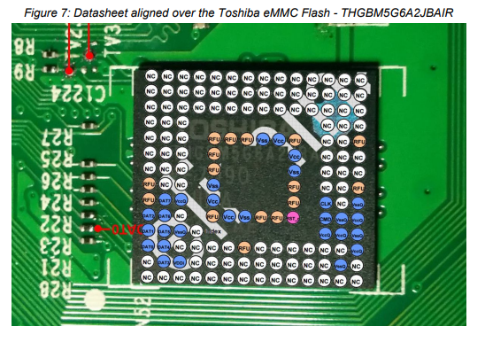
To these:
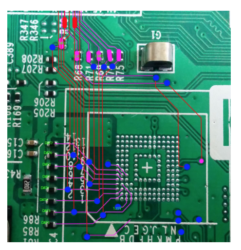
For these lines:
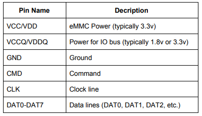
It might even be worth making a quick breakout pcb to sit between the interposer and the board with pads to solder to for a much cleaner job. I might have a look at doing that for you tomorrow

Edit: That little guide you have given me is super useful, i'll get the oscilloscope out tomorrow and test all the signals to make sure we know whats going on and verify its the same/similar to that pinout above. Ill then throw together some sort of interposer for the interposer and get one of those free pcb's you can get printed up.

Or not we are going to do it the hard way!!
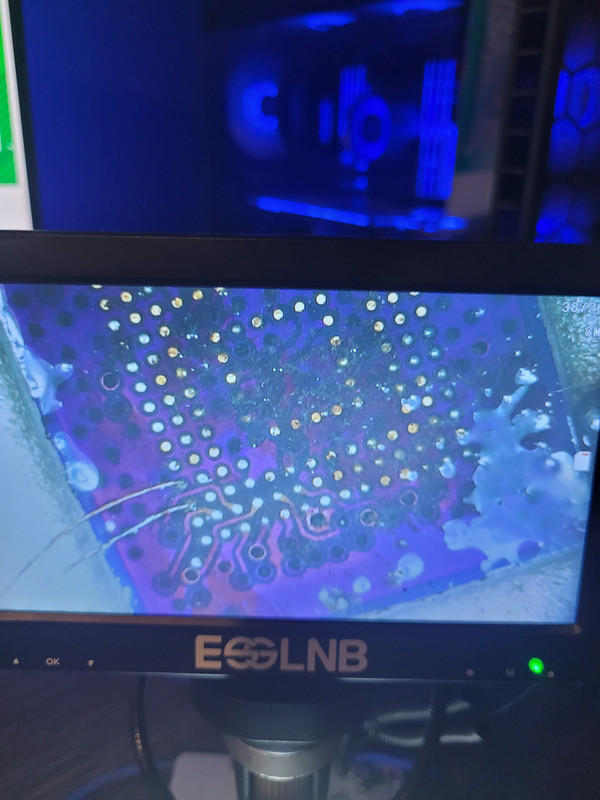
First two data lines on the interposer

 although I may take them off, put the connector on the interposer first and then solder up all the lines
Edit2: Already took them off forgot to flip the picture to be interposer side. Also laid a bit more solder down on the interposer on all the pads we need to solder to, first off and to test ill run all the data lines, a couple of vcc lines, a couple of vss lines, clk, cmd, a couple of vssq and a couple of vccq. So 18 jumpers from the interposer in total, some ill connect directly to the socket (you are right you pretty much got away with it but all the resting pins are gone), the rest ill push to the the resistors. I think it should be pretty clean when we are all done. With a bit of luck we might get to a point where we can test to see if it works some time tomorrow.
Last edited:
Soldato
- Joined
- 1 Oct 2006
- Posts
- 14,223
You maniac!  So where do you think you'll seat the interposer in the end? Off to one side with wires running to the pads? What gauge wire are you using to create those traces out of interest?
Those connectors aren't too bad to sweep solder. I ordered the parts to make up the eMMC modules that connect to the interposer, and the last parts arrived yesterday. Inspired by your efforts I had a go myself, and faired better with soldering (more so than DEsoldering). Fortunately the eMMC chips were pre-balled, so with a little help from the hot bed on my 3D printer and some air from the top I managed to get it seated. It only bloody works lol.
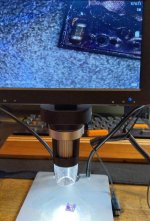
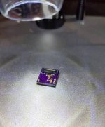
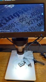
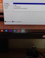
I know my limitations now, SMD soldering I can do. Desoldering and the inevitable trace repair (lol) not so much. I really should invest in a hot plate or something.
 So where do you think you'll seat the interposer in the end? Off to one side with wires running to the pads? What gauge wire are you using to create those traces out of interest?
 Those connectors aren't too bad to sweep solder. I ordered the parts to make up the eMMC modules that connect to the interposer, and the last parts arrived yesterday. Inspired by your efforts I had a go myself, and faired better with soldering (more so than DEsoldering). Fortunately the eMMC chips were pre-balled, so with a little help from the hot bed on my 3D printer and some air from the top I managed to get it seated. It only bloody works lol.


I know my limitations now, SMD soldering I can do. Desoldering and the inevitable trace repair (lol) not so much. I really should invest in a hot plate or something.
You maniac!So where do you think you'll seat the interposer in the end? Off to one side with wires running to the pads? What gauge wire are you using to create those traces out of interest?
Those connectors aren't too bad to sweep solder. I ordered the parts to make up the eMMC modules that connect to the interposer, and the last parts arrived yesterday. Inspired by your efforts I had a go myself, and faired better with soldering (more so than DEsoldering). Fortunately the eMMC chips were pre-balled, so with a little help from the hot bed on my 3D printer and some air from the top I managed to get it seated. It only bloody works lol.
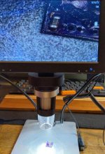
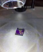
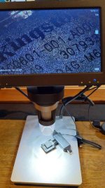
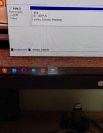
I know my limitations now, SMD soldering I can do. Desoldering and the inevitable trace repair (lol) not so much. I really should invest in a hot plate or something.
The wire is 0.1mm, it needs to be smaller than the pads so not to put excessive pressure on them and pull the pads off.
I'll probably seat the interposer directly over the old emmc and run the wires under the interposer.
That's a solid effort on that interposer! I'm pretty busy work wise today but I'll prod and poke at it over the next few days and keep updates in here.
Bga just takes a lot of practice. Trust me I've messed up enough switch boards to know its not an easy task.
Soldato
- Joined
- 1 Oct 2006
- Posts
- 14,223
Well, that's definitely something to aspire to but I don't think I have a steady enough hand to do that. More practice!
I see got you, so that wire is insulated then?
BGA153 is perhaps a little advanced for my first foray into the form factor. Probably should have started with a BGA16 or something!
No rush, gives me more time to make up another module and get the rest of the resistors/caps on there to smooth out the voltages.
Cheers!
I see got you, so that wire is insulated then?
BGA153 is perhaps a little advanced for my first foray into the form factor. Probably should have started with a BGA16 or something!
No rush, gives me more time to make up another module and get the rest of the resistors/caps on there to smooth out the voltages.

Cheers!
Well, that's definitely something to aspire to but I don't think I have a steady enough hand to do that. More practice!
I see got you, so that wire is insulated then?
BGA153 is perhaps a little advanced for my first foray into the form factor. Probably should have started with a BGA16 or something!
No rush, gives me more time to make up another module and get the rest of the resistors/caps on there to smooth out the voltages.
Cheers!
It is indeed, it's insulated magnat wire
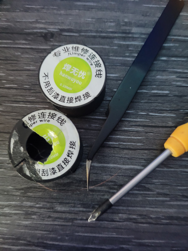
This is it next to some tolls to try and give an idea of how small it is.
Getting a little behind on the stuff in the queue so last night I decided to fix the ps4 I got sent with pretty extensive port damage.
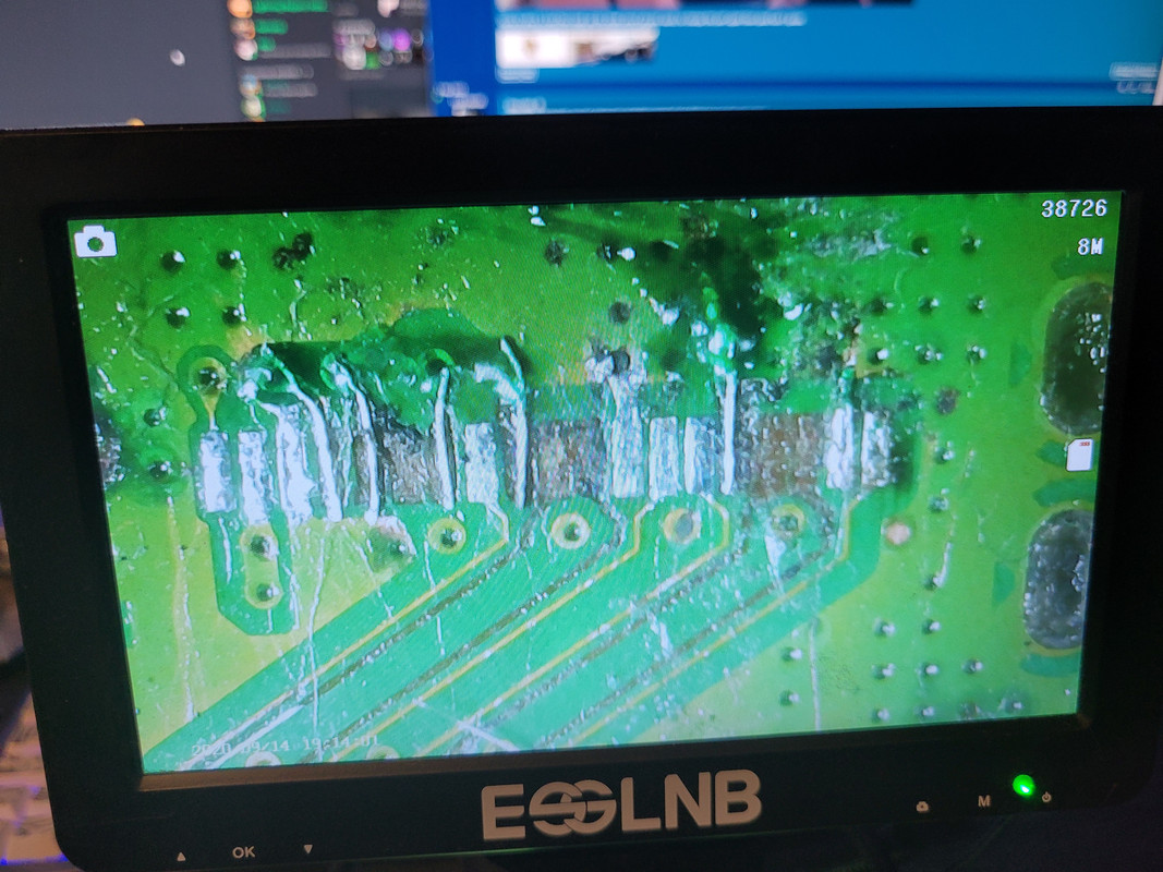
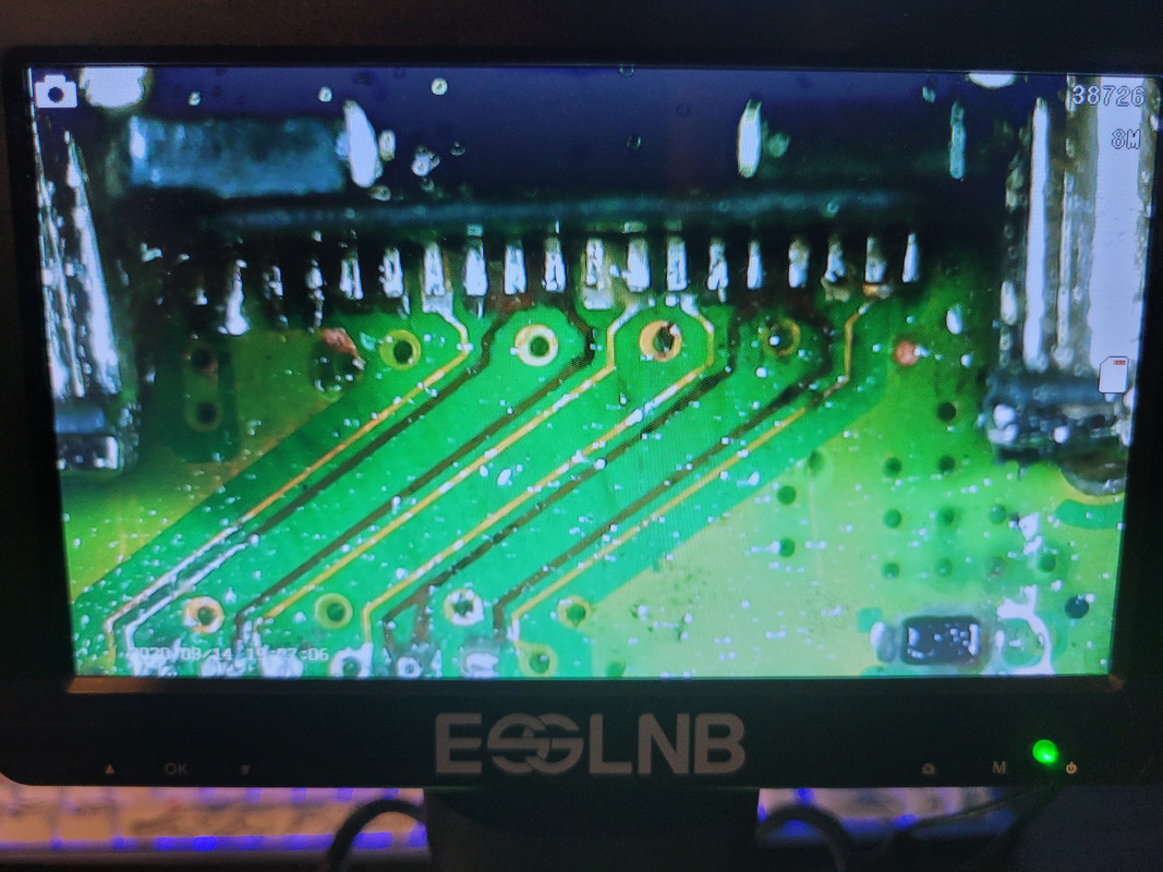
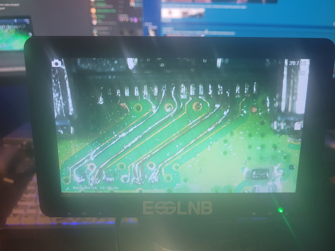
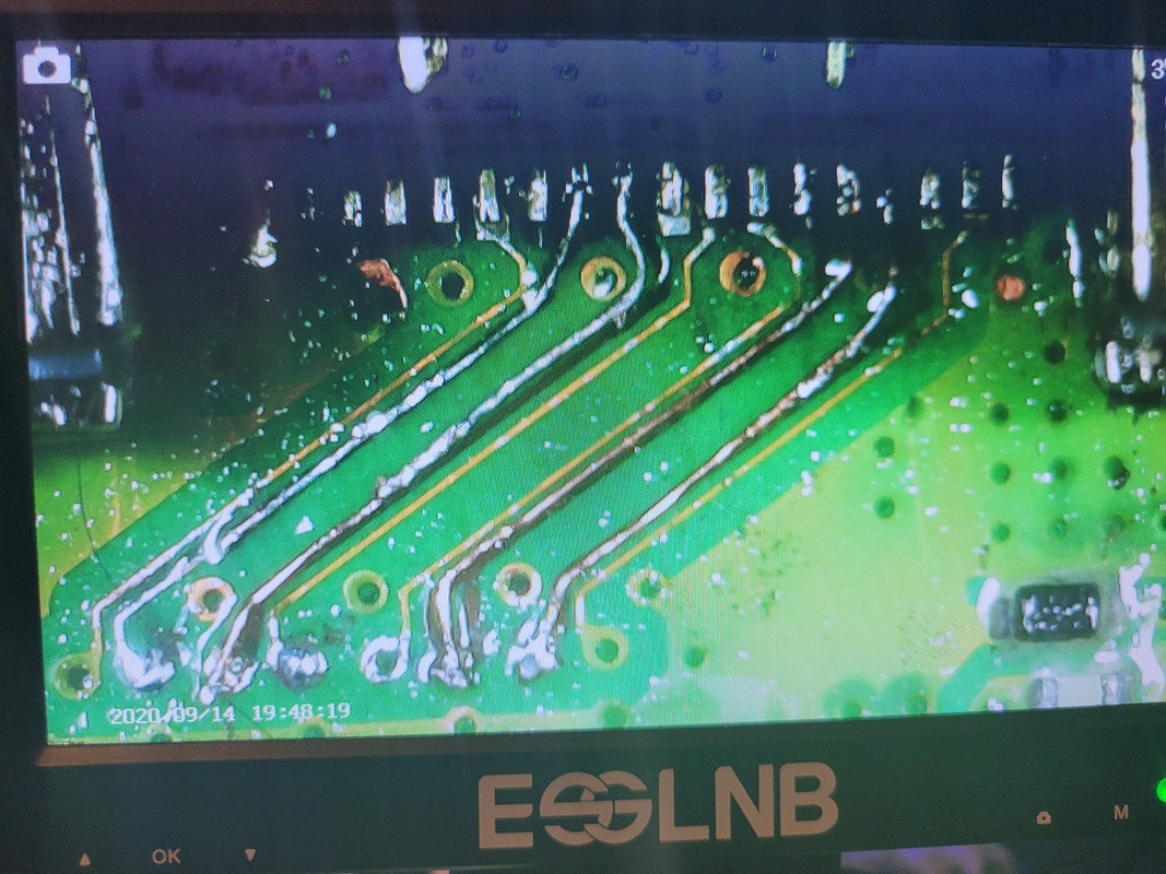
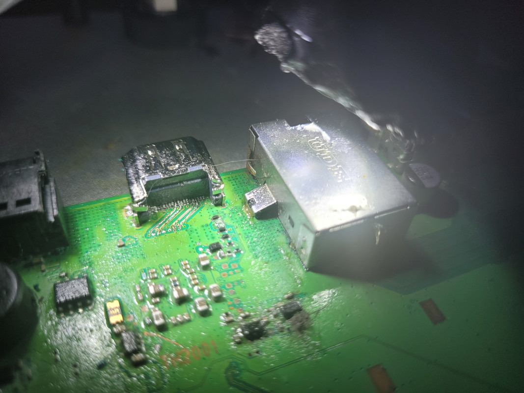
10 of the 19 hdmi traces were ripped off so we had to rebuild it all. Waiting on some parts from the owner now as I can't put it back together as they forgot to send me all the screws/clamps and a few cables from inside the console. Contacted them last night and they are on the way


10 of the 19 hdmi traces were ripped off so we had to rebuild it all. Waiting on some parts from the owner now as I can't put it back together as they forgot to send me all the screws/clamps and a few cables from inside the console. Contacted them last night and they are on the way

Soldato
- Joined
- 1 Oct 2006
- Posts
- 14,223
How the heck did they manage that? Swinging it around by the HDMI cable? 
Nice neat fix that, is that overlaying magnet wire on top of the traces?

Nice neat fix that, is that overlaying magnet wire on top of the traces?
How the heck did they manage that? Swinging it around by the HDMI cable?
Nice neat fix that, is that overlaying magnet wire on top of the traces?
Yea I am just replacing what was ripped out so I ran 0.1mm magnat where the traces used to be, because the old trace is ripped out it makes a nice little crevice in the board that you can sit the wire in and sort of massage it into place. I replaced all of the ones that had connection at the rear of the board first, then used a mask to set them in place. Once in place and solid I sat the port on soldered down the available pins and connected up the rear jumpers. I then ran all of the front traces so a total of 10 jumpers. Ill test this when parts arrive and then if all good ill pull it apart and mask it all up to make it nice and clean.
My guess is it was done during a failed port repair, somebody imo tried ripping the port off without all of the solder properly melted and ended up just ripping everything up.


