Project: Self-Inflicted

Soldato
OP
Joined
4 Jun 2007
Posts
2,617
Location
Watford, UK
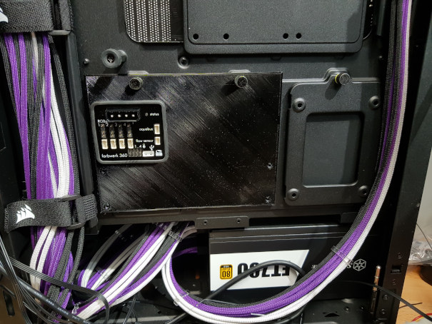
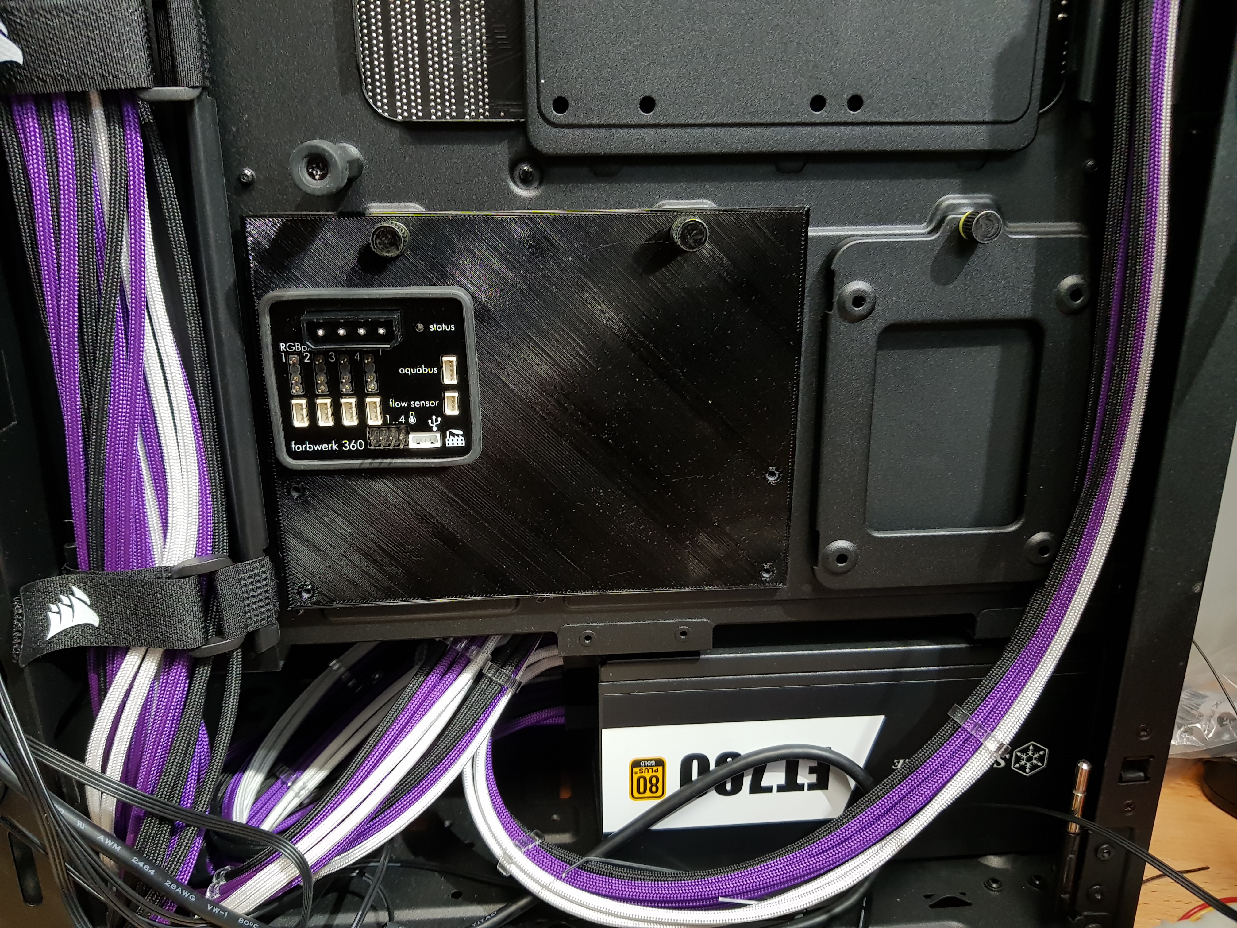
Made a plate to mount the Aquaero (which isn't coming out the donor machine until the last minute) and the Farbwerk. It co-opts the 2½" SSD mounts at the back of the motherboard so that it's tidy and I can - with the help of some overpriced 90° molex power connectors - get the door shut too!
A few iterations to get the prongs that fit in the slots at the bottom right and then a 5 hour print.....that didn't fit! Not entirely sure how I got the top screw holes in the wrong place after careful measuring and layout....but I did, and by about 4mm! A quick tweak at midnight and it was ready for the morning. M3 tap through the 3D printed threads and it fits!


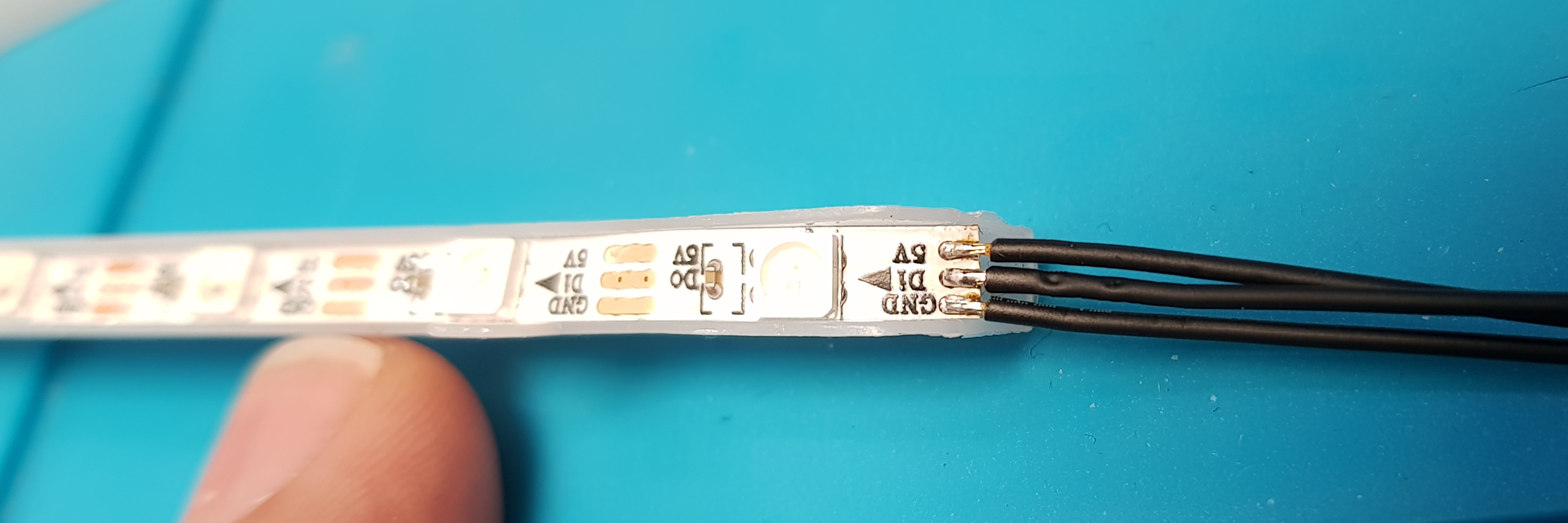
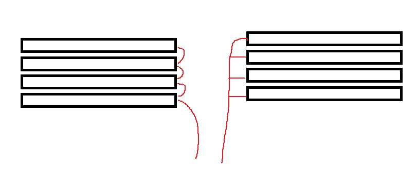
Right, time to bash my sanity against some tiny wiring!
 
Soldato
OP
Joined
4 Jun 2007
Posts
2,617
Location
Watford, UK
PETG. It's my go-to filament simply because I don't have to run the layer fan. It's noisy (very bad and odd implementation of PWM for that on my Ender 5's controller) and the overspill from my hotend fan is enough. I tend to print the threads as modelled and then tap them as they'll end up too small every time - but at least the material is in the right place. They tend to be tight but that's a good thing for not falling apart. I've got 3 perimeters set at the moment but I'm pretty sure I've done it ok with 2. The base board is 3mm thick and threaded the whole way through.
Similarly, if I need a hole to be 3mm, I tend to print it as 3mm and then run a reamer through it when it inevitably comes out too small.

I'm not necessarily expecting it to withstand hundreds of screw/unscrew cycles as once they're mounted, they shouldn't need to come off very often. I could put some inserts in if they wore out but I suspect a re-print to add some holes for something else or a design-change will occur before that need arises.
Similarly,
 
Soldato
OP
Joined
4 Jun 2007
Posts
2,617
Location
Watford, UK
Well, THAT was fun! :rolleyes: 
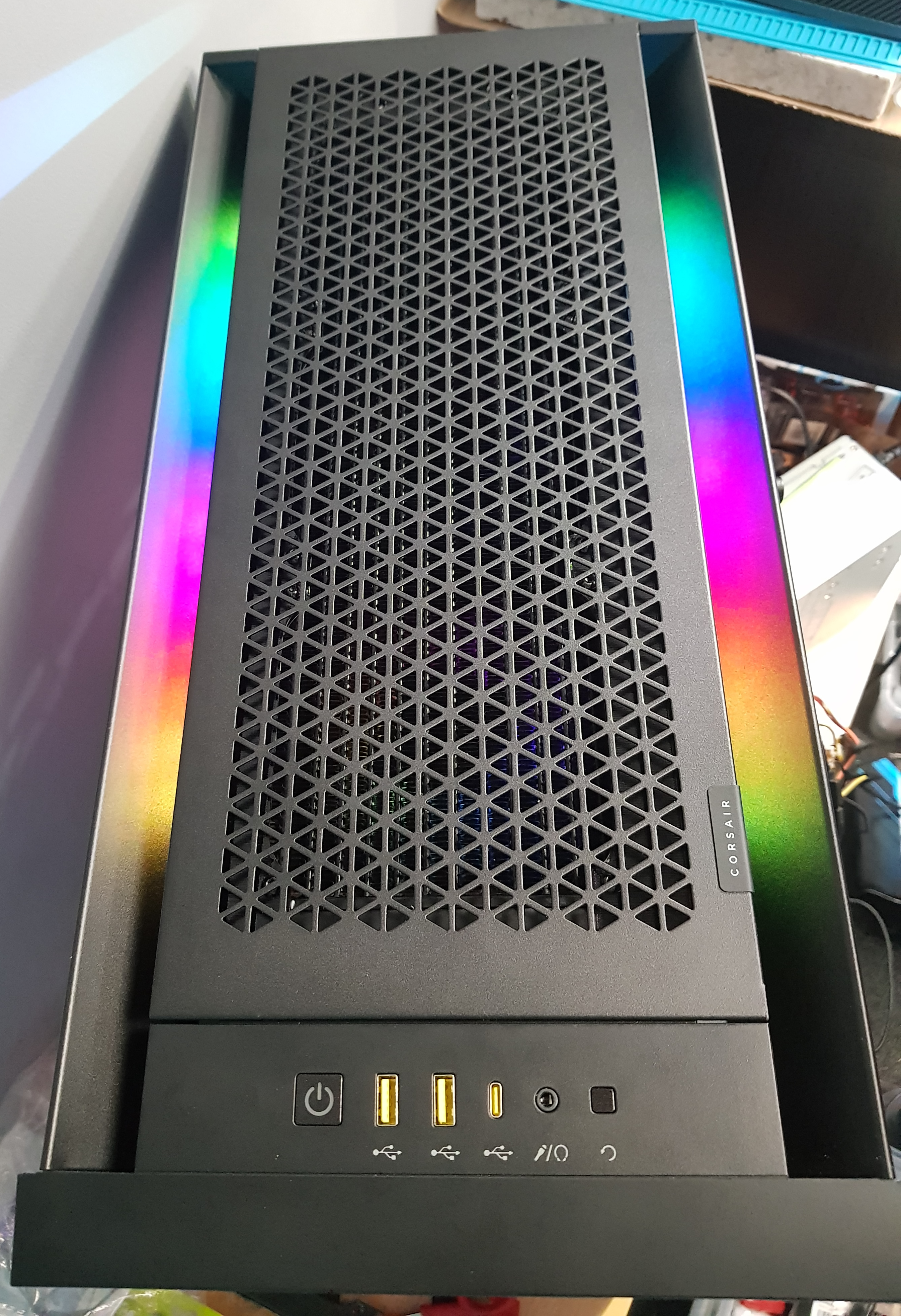
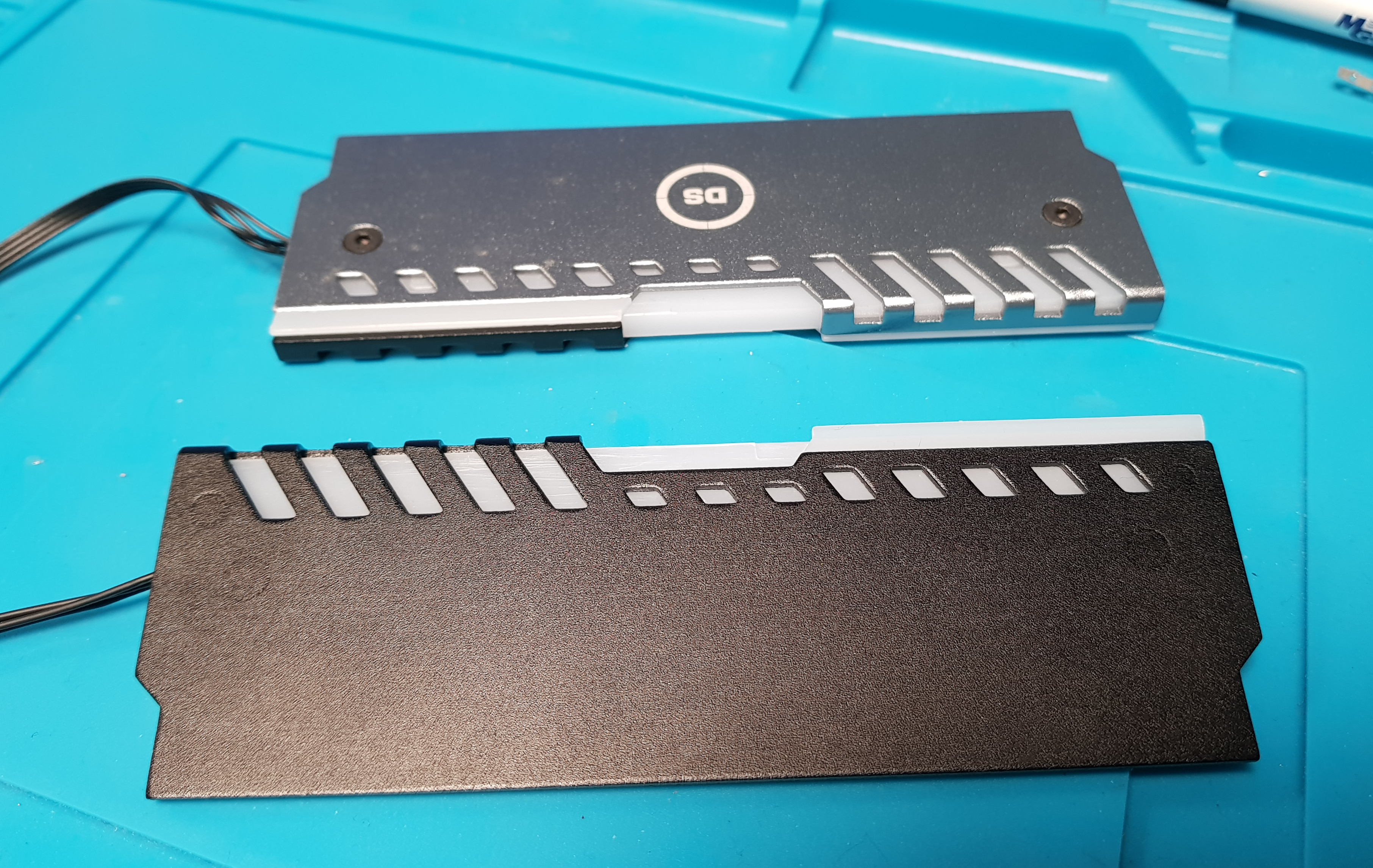
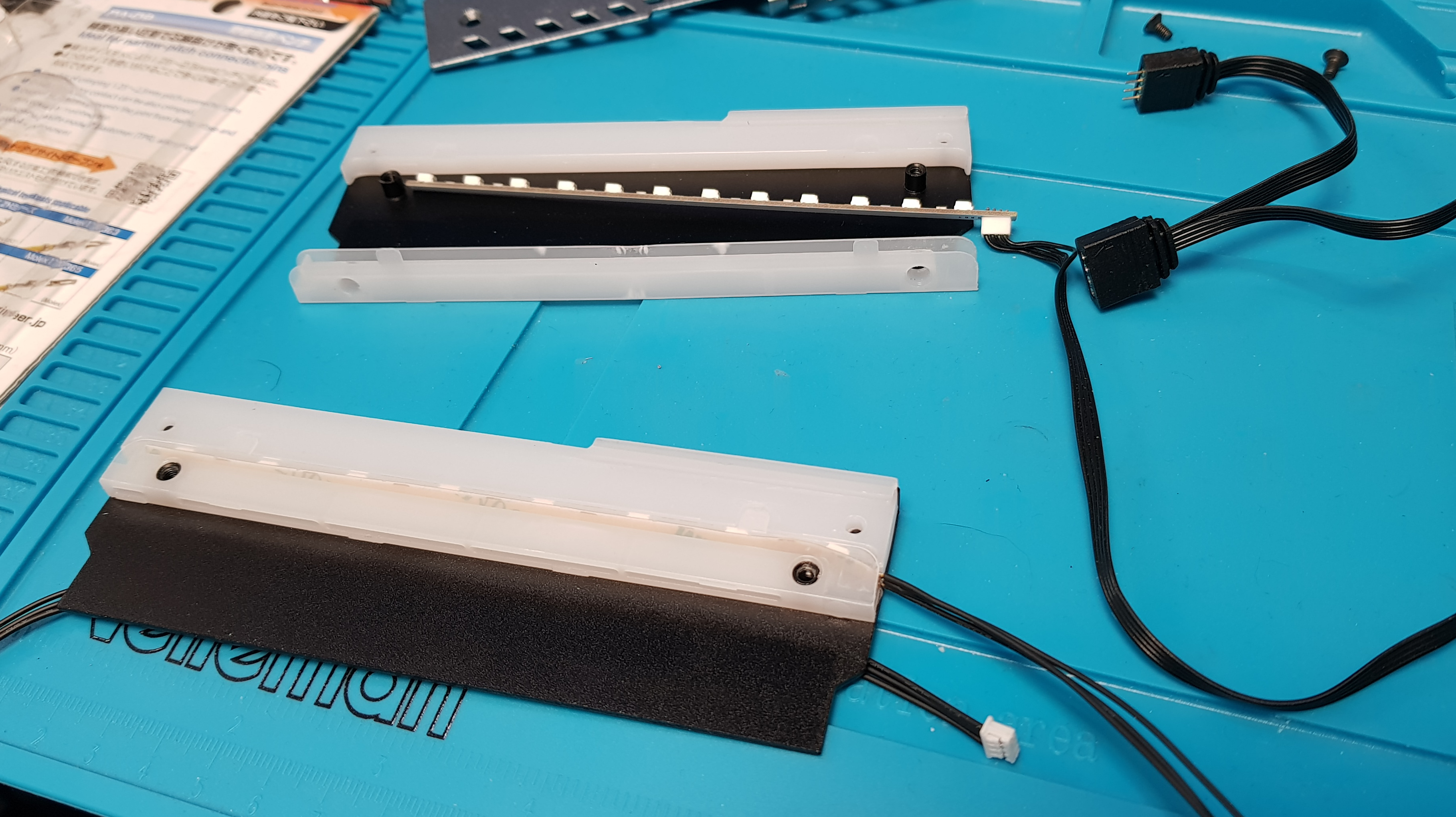
They call them "Pico" for a reason! Fiddly little blighters they are. Quite pleased with the result though. Threads nicely under the rad so you can't see it once the grill is on.


And.....DISCO!


Plan is to print some shields so you can't see the LEDs directly through the top grill but they illuminate the cavity.
 
Soldato
OP
Joined
4 Jun 2007
Posts
2,617
Location
Watford, UK
I think it's less noticible in the flesh so to speak - exaggerated by the camera. But I'll have another look when I've finished swearing at the dimensions of this shield - the centre-to-centre hole dimensions are giving me grief by not fitting even though they come out as exactly 105mm however I measure it. I've just made sloppier tolerances on the holes so the screws will go it....sshhhh, don't tell anyone! :D
I think I may have some frosted quadrant from some LED profiles in the loft....which will, of course, have vanished into thin air if I go looking for it!
 
Soldato
OP
Joined
4 Jun 2007
Posts
2,617
Location
Watford, UK
Found some, cut some, blue-tack'd it in place....and you're right. However, I fitted the first shield that actually fits and I think the reflection off the underside of it achieves very nearly the same sort of diffusion but without fraying my sanity more than it already is!
 
Soldato
Joined
26 Sep 2010
Posts
7,154
Location
Stoke-on-Trent
Whatever works! I just hate hotspots lol

Which is why I'm monumentally pee'd off that my motherboard lighting ring is full of hotspots :mad: 
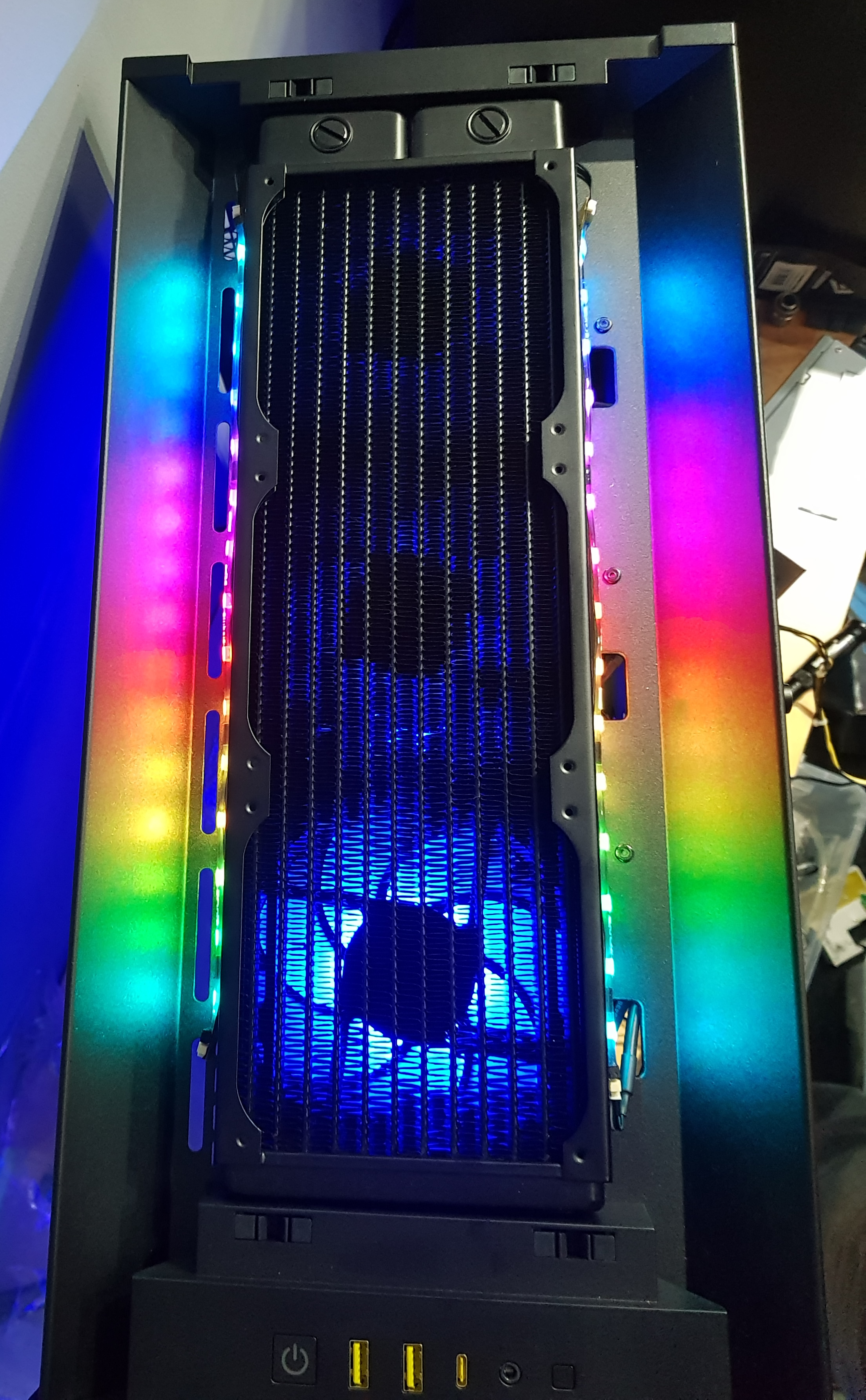
and add the fact that cool white LED strips illuminating Opal 050 acrylic (y'know, the pure white stuff used in lightboxes) HAS A MOTHERTRUCKIN' YELLOW CAST TO IT.

Oh look, pure white EL wire that's only 1mm OD and runs on 12V...is my OCD rage worth dropping £20 for an experiment on a project that is never likely to get finished?
 
Soldato
OP
Joined
4 Jun 2007
Posts
2,617
Location
Watford, UK
Probably. But not necessarily for that exact reason. I tend to cave when I realise that I'm just not going to let it go so I can either chew myself up about it or drop the ten/twenty quid and hope it goes well. Not condoning this behaviour, you understand....just saying that sometimes the path of...slightly less resistance, is worth the price.
Incidently, I'm the same about LED lamps that you can see. The high-level brake lights of a lot of cars irritate me for that reason. Not so much on whoever's car it is but I want to do one on mine instead of the factory one that's at the bottom and blocks out half the view of the road - GENIUS design, that.
 
Soldato
Joined
26 Sep 2010
Posts
7,154
Location
Stoke-on-Trent
just saying that sometimes the path of...slightly less resistance
Gonna be massively more resistance if I go for it :p

I'll have to also change the SSD rings to use the EL wire as well as all lighting elements are powered from that cute SATA 12V PCB. So I'd have to rig the 12V inverter to send its AC output into the PCB and then drive 3 runs of EL wire from that, replacing all the connectors to 2-pin Dupont because that's how it was originally intended.

And assuming nothing goes weird sending an AC signal through that PCB, I'll have to actually cut, terminate and rewire 2 lengths of 1mm OD EL wire.

So yeah, path of slightly less resistance is to just crank the brightness of the LED rings to max for the final photos (in 2027 at this rate), then just suck up the hot spotted yellow cast when the LEDs are dimmed to usable levels, or just turn them off rendering one of the original design elements redundant :D
 
Soldato
OP
Joined
4 Jun 2007
Posts
2,617
Location
Watford, UK
3D Printer has finished. In hindsight I probably should have designed an overlap between the two parts to block the light - too big to print as one long part - but the two seem to close up pretty well with a little trimming and aligning. You can see in the second pic how it's a lot less hot-spot'y now.


Found some 3M VHB (double-sided adhesive clear gum) to stick the ends of the strips down as they were starting to peel already. Hopefully that should keep them in place.
 
Soldato
OP
Joined
4 Jun 2007
Posts
2,617
Location
Watford, UK
4mm wide LED strip just arrived to convert the RAM heatsinks from RGB to ARGB. Yay! How wide is a 4mm strip? That's right, 5.6mm! No way that's going to fit into the available space. Also it's made with 5050 LEDs (for those that aren't aware, that's 5mm x 5mm) instead of 3535 LEDs so it HAS to be the wrong item sent. Good job I've not waited over two weeks for them to arrive or I might be annoyed! *facepalm*
 
Soldato
OP
Joined
4 Jun 2007
Posts
2,617
Location
Watford, UK
Ok, new toys arrived and this time in the correct size. So I'd like to ask for opinions please.

These are the RAM heatsinks. One of you is going to recognise them! They are the only RGB component in the system; the rest are all aRGB/DRGB/RGBpx - pick your preferred acronym. I want to make everything ARGB as it will simplify things to have one controller instead of two and potentially it'll look odd if the RAM can't match the rest. I don't want to replace the RAM with ready-made ARGB RAM for two reasons: 1. I'm a cheapskate :D and 2. It requires a different control software and I'd rather everything was on one controller. So I want to convert them.


First question. Do I leave them half silver, half black or do I spray the silver side black?

The internals look like this. RGB at the top and my prototype conversion at the bottom. I can seat the tape better once I'm happy with it but actually it doesn't degrade the effect you can see from the outside.
You can also see the loop-through RGB connectors on the old.


This is the (horribly over-exposed) strip and the connections to it.


Next question then. Do I hardwire all four heatsinks together in a chain by soldering a shorter length of wire over the top piggy-back style and maybe backed up with some silicone or hot-glue as insulation or do I try to emulate the loop-through plugs setup that was there originally. My gut is to just solder them in a chain as I think that will be neater (easier to hide the wiring) and I can't really think of a good way of doing connectors that are a less hideous mess than the previous ones.....but I'm open to suggestions! I could also try to solder the wires in T connections externally rather than on the strip - more fiddly but may be necessary if the piggy-backing doesn't work well.

It's also worth noting that by piggy-backing the wiring, I'd not technically be chaining them together, they'd be split. The difference being that if we have 8 LEDs in each module, with them split they appear to the controller as 8 total LEDs so each stick will do the identical thing since each of them has LEDs numbered 1 to 8. I could run the data wire to the next module from the other end of the strip and that would result in a proper chain with the first module having LEDs numbered 1 to 8, the second having 9 to 17 and so on. There are pros and cons to this: it would allow each module to be different....but I'm not sure that's a good or necessary thing. The downside is that for a 'rotating rainbow' - which I suspect may be what ends up being used most - if you have 8 LEDs and that's it, you can make the rainbow 8 LEDs wide and you get one of each colour of the rainbow and they cycle. OR you can make the rainbow up to 90 LEDs (max for channel) wide and you get a section of the rainbow scrolling through...which tends to look better on straight strips. It works because the other 82 LEDs don't display as they don't exist. You can't do that if the next numbered LEDs do exist on another module - or you can but the effect you'd get would be that the rainbow cycled down one module and then down the next...if that makes sense.
 
Soldato
Joined
26 Sep 2010
Posts
7,154
Location
Stoke-on-Trent
For visual tidiness of wiring coming out of the heatspreaders, I'd say run each DIMM into a single connector, so the RGB effect will be the same on each set of 8 LEDs. I can't think of a tidy way to run a loop between the two DIMMs.
 
Soldato
OP
Joined
4 Jun 2007
Posts
2,617
Location
Watford, UK
It's going to be a four-dimm setup (4x4GB) so I have double the number of connections to test my sanity with! There's no way I can get more than one wire into a picoblade connection. I could probably do two into some other type of connection but definitely not four. The way I see it, the options are these...but with three wires where I've only drawn one. Excuse the mashed up pic :D

RAM-LEDs4.jpg


What do you think on the silver half too?
 
Soldato
Joined
26 Sep 2010
Posts
7,154
Location
Stoke-on-Trent
Rightio...

Regardless of which way you do this, you're going to have 12 wires visible and it's potentially scruffy any which way. I don't think triple 3-wire loops betwixt the DIMMs will be viable because you either make then short enough to loop as invisibly as possible (which is some ballache soldering for you :p) or make them long enough to be practical and then try to tuck them away somewhere. Or, you you somehow put 4 Y splits into 3 wires and somehow deal with a mass of cabling.

So, here is a 3rd option, and what I personally would do: PCB splitter :D

Each DIMM has its own cable run, so sleeve up 3 wires into a single unit per heatspreader, and replace the connectors with 4x1 Dupont (or 3x1 if you can find them). Then, get yourself some stripboard and slap onto it the corresponding Dupont headers. You can then plug each heatspreader cable into the stripboard and have each channel fed by a single source. So do yourself a suitably long 3-wire Picoblade cable and either solder it to the stripboard, or do a 5th Dupont connection for ease of disassembly and routing.

You can shove the splitter and all the wire wherever you want then to hide them. So for example, you can run the heatspreaders upwards and tuck the cables round the back of the motherboard; the small distance from the top of the RAM slots to the top of the board is short enough to effectively hide the cables (especially if sleeved in black), then mount the splitter on the back too, with the RGB header cable routing wherever you need to.

As for heatspread colour, I'm going to be a total pain in the ass and say "none of the above". Personally, at the very least I'd go white to match your IO cover and chipset heatsink, with a purple diagonal strip for accent. Or go balls-deep with it and replicate the entire chipset heatsink arrangement and go 50/50 black and white with diagonal strips in silver and purple to accent.

Y'know, just to make your life more complicated.
 
Soldato
OP
Joined
4 Jun 2007
Posts
2,617
Location
Watford, UK
Hmmm, that's certainly some things to think about. I think I can come up with a half-decent excuse not to go to those lengths for the RAM :D Because of their angle and how closely packed together they are, there's only really one face you'd see at all so it's really more about the top edge of them. I think silver is definitely wrong - not painfully so but still wrong. I'd not thought about white rather than black....but I'm in two minds whether there's too much white already. That really gives me a choice of:

Black - Black
Black - White
Black - Purple

And if I go purple, I'd probably end up having to buy all four cans because you just know that whichever one you picked would be wrong! I'd be swaying towards the Kobra Melanzana (See Andy, I do listen!) or Montana Galaxy If I had to pick just one....which is definitely something appealing about just making it black! Also, I think if I painted them in purple, I'd just have to redo the purple that went on the board to match. Damn, how did I get here from wiring?! :confused::cry:

RAM-LEDs5.jpg


I don't hate the idea of four neat sleeved wires leaving the board vertically, wrapping over the top and into the void at the back which actually has its own door to cover your sins.....which, of course is why I'm making it look pretty :rolleyes: Individual, pluggable runs would definitely make it easier to make and manage. There was a mount on the back for a fan hub that I thought about pressing into service....but it's more complicated than it needs to be with separate power and a PWM repeater. The mount points could be co-opted though! If I go PCB, are there any prototype fabs you'd recommend/avoid?
 
Soldato
Joined
26 Sep 2010
Posts
7,154
Location
Stoke-on-Trent
Just emailed you a spitball for the RAM.

As for PCB, unless you want to be super fancy, just go with stripboard. It's 2.54mm pitch, so are Dupont connectors, and all you're doing is connecting pins along common lines, so stripboard is perfect. For my PCBs I used JCPCB out of Chinaland because they're also tied with EasyEDA for designing the circuits and PCBs (web UI) and a components company I forget the name of.

At the time they did a special deal on PCBs 100mm x 100mm max size, 2 layer 1oz copper were heavily discounted, and recently stopped charging extra for common alternate colours. this was a few years ago now (ffs I'm taking forever to do this project :( )
 
Back
Top Bottom